Cisco Cloud Campus LAN Design Guide (CVD)
Available Languages
Bias-Free Language
The documentation set for this product strives to use bias-free language. For the purposes of this documentation set, bias-free is defined as language that does not imply discrimination based on age, disability, gender, racial identity, ethnic identity, sexual orientation, socioeconomic status, and intersectionality. Exceptions may be present in the documentation due to language that is hardcoded in the user interfaces of the product software, language used based on RFP documentation, or language that is used by a referenced third-party product. Learn more about how Cisco is using Inclusive Language.
This document provides a pre-validated design and deployment guide for a Cisco Campus LAN with Catalyst® Switches and Access Points running in either Cloud Managed or Cloud Monitored mode alongside the various design guidelines, topologies, technologies, configurations, and other considerations relevant to the design of any highly available, full-service campus switching fabric. It is also intended to serve as a guide to direct readers to general design and best practices for Cloud-based Cisco Campus LAN.
The LAN is the networking infrastructure that provides access to network communication services and resources for end users and devices spread over a single floor or building. You create a campus network by interconnecting a group of LANs that are spread over a local geographic area. Campus network design concepts include small networks that use a single LAN switch, up to very large networks with thousands of connections.
The campus wired LAN enables communications between devices in a building or group of buildings, as well as interconnection to the WAN and Internet edge at the network core.
Specifically, this design provides a network foundation and services that enable:
● Tiered LAN connectivity
● Wired network access for employees
● IP Multicast for efficient data distribution
● Wireless and Wired infrastructure ready for multimedia services
Cisco's Campus LAN architecture offers customers a wide range of options. The Catalyst portfolio with Digital Network Architecture (a.k.a. Cisco Catalyst Center, previously known as Cisco DNA Center) provides a roadmap to digitization and a path to realizing immediate benefits of network automation, assurance and security with an on-prem operating model. The Catalyst portfolio with Meraki Dashboard enables customers to accelerate business evolution through easy-to-use cloud networking technologies that deliver secure customer experiences and simple deployment of network products with a cloud-first operating model.
The proposed architecture enables you to build secure, scalable, and robust enterprise networks. Since the design involves deploying Catalyst platforms in either Cloud Managed or Cloud Monitored modes, special attention should be given to proper planning and design to ensure interoperability and performance.
Designing a LAN for the campus use case is not a one-design-fits-all proposition. The scale of campus LAN can be as simple as a single switch and wireless AP at a small remote site or a large, distributed, multi-building complex with high-density wired port and wireless requirements. The deployment may require very high availability for the services offered by the network, with a low tolerance for risk, or there may be tolerance for fix-on-failure approach with extended service outages for a limited number of users considered acceptable. Platform choices for these deployments are often driven by needs for network capacity, the device and network capabilities offered, and the need to meet any compliance requirements that are important to the organization.
This document provides a pre-validated design and deployment guide for a Cisco Campus LAN with Catalyst Switches and Access Points running in either Cloud Managed or Cloud Monitored mode alongside the various design guidelines, topologies, technologies, configurations, and other considerations relevant to the design of any highly available, full-service campus switching fabric. It is also intended to serve as a guide to direct readers to general design and best practices for Cloud-based Cisco Campus LAN.
Cloud management and monitoring for Cisco Catalyst
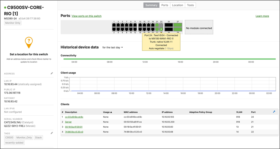
Selected Cisco Catalyst devices (9200, 9300, and 9500) are capable of connecting to the Meraki Dashboard for monitoring purposes. This offers dashboard monitoring and insights for Catalyst devices including visibility into some configuration items. However, please note that this does not offer full management in Meraki Dashboard. (i.e. No configuration changes in Meraki Dashboard). Please see the following snapshot of C9500 switches/stacks in the Meraki Dashboard:
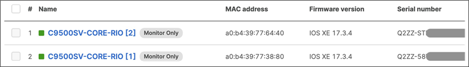
For more information about Cloud Monitoring, please refer to this article.
Campus LAN architecture with Cloud management
Please refer to the following proposed architecture diagram as a reference for this CVD:

To achieve a robust, reliable, high speed and Future Proof Campus LAN, the following components are part of this architecture:
| Component |
SKU |
Capabilities |
Management Platform |
Integrations |
| Wireless LAN |
MR55-HW (Or MR56/57) with LIC-ADV And C9166-MR (1) with LIC-ADV |
WiFi6 High-density Wireless Access points mGig uplinks Adaptive Policy |
Meraki Dashboard |
Cisco ISE (Optional) Azure Active Directory (Optional) |
| Access Switches |
And C9300-24P M(1) with C9300-NM-8X and LIC-MS390-24A |
Physical Stacking with StackPower Up to 40G Uplinks Layer 3 capabilities |
Meraki Dashboard |
Cisco ISE (Optional) |
| Collapsed2 Core Switches |
C9500-24Y4C (Monitor Only) |
Up to 100G Uplinks Secure segmentation with SD-Access MACSec 6.4 TB switching capacity |
Meraki Dashboard (Monitor Only) |
|
| WAN Edge and UTM |
MX250 in warm-spare configuration (2) with LIC-MX250-SDW OR A Catalyst SD-WAN solution |
10G SFP+ WAN 10G SFP+ LAN 1G SFP LAN Security (UTM) and SD-WAN 4 Gbps Firewall Throughput 2 Gbps SD-WAN Throughput |
Meraki Dashboard |
|
This document will provide three options to design this campus architecture from a logical standpoint, which are outlined below (each with its own characteristics):
Layer 2 Access with Native VLAN 1
This option assumes that your Spanning Tree Protocol (STP) domain is extended all the way to your core layer. It offers great flexibility in terms of network segments as you can have your VLANs spanning over the different stacks/closets. However, the STP configuration and tuning is crucial since the Catalyst platforms can run different STP protocols than the Meraki MS390 switches.
Pros:
● Flexibility in your VLAN design
● Facilitates Wireless Roaming across the whole campus
● Easier to deploy and consistent configuration across the entire Campus LAN
Cons:
● Non-deterministic route failover
● Slow convergence
● Different STP protocol support on Cloud Monitored and Cloud Managed Catalyst Switches
● The possibility of VLAN hopping
Layer 2 access without Native VLAN 1
This option is similar to the above except that VLAN 1 does not exist and the default Native VLAN 1 is replaced with another non-trivial VLAN assignment which can be considered a more preferable option for customers as its separate from the Management VLAN
Pros:
● Flexibility in your VLAN design
● Facilitates Wireless Roaming across the whole campus
● Easier to deploy and consistent configuration across the entire Campus LAN
● Minimize the risk of VLAN hopping
Cons:
● Non-deterministic route failover
● Slow convergence
● Different STP protocol support on Cloud Monitored and Cloud Managed Catalyst Switches
| Note: Please note that the recommended Spanning Tree Protocol for Cloud-based Cisco Campus is Multiple Spanning Tree Protocol since it eliminates configuration and troubleshooting issues on the different platforms. As such, if you configure other protocols on (e.g. Per VLAN Spanning Tree [PVST]) on your network, then please note that VLAN 1 is going to be essential as backward compatible Bridge Protocol Data Units (BPDUs) only run in VLAN 1. |
Layer 3 access
This option assumes that your Open Shortest Path First (OSPF) domain is extended all the way to your core layer and thus there is no need to rely on STP between your Access and Core for convergence. It offers fast convergence since it relies on Equal-cost multi-path routing (ECMP) rather than STP layer 2 paths. However, it doesn't offer great flexibility in your VLAN design as each VLAN cannot span between multiple stacks/closets.
Pros:
● Deterministic route failover
● Fast convergence
● Relies on either stacking or gateway redundancy at upper layers
Cons:
● VLANs cannot span multiple stacks/closets
● Your backbone area size can be unmanageable
● Layer 3 roaming is not possible without a concentrator
This CVD offers the design and configuration guidelines for ALL options above.
Campus LAN planning, design, and configuration
The following section provides information on planning your solution and ensuring that you have a successful deployment. This will include gathering the design requirements and planning for your Cloud-based Cisco Campus LAN architecture based on your own requirements.
Prior to proceeding to plan for your deployment, please refer to the Campus LAN Design Best Practices Guide which can be used to guide you through the planning phase of designing your Campus LAN.
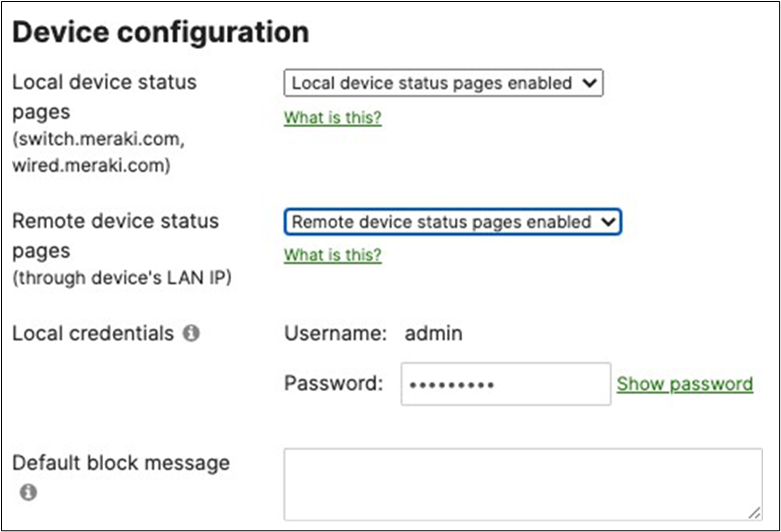
Meraki cloud administration and management
If you don't have an account on the Meraki Dashboard, create one following these steps:
1. Generate an API Key for your account following these steps.
2. Claim your order(s) or serial number(s) into your Meraki Dashboard account.
3. Add your devices to existing networks or create new networks as required.
4. Configure firmware upgrades for your network(s) with latest Stable or RC releases for each device type (Please check the firmware changelog for platform-specific details).
5. Configure your network(s) with the correct time zone from Network-wide > Configure > General (This is key for reporting and firmware upgrades).
6. Configure your network(s) with the desired upgrade date and time.
7. Configure the MR upgrade behavior as desired.
8. Ensure that your Campus LAN has access to the internet for management purposes.
9. Ensure that Meraki Cloud is accessible and that all required ports are opened where applicable (information can be found in Dashboard).
10. Ensure that there is sufficient bandwidth for firmware upgrades as they tend to be large in size.
11. Ensure that only current administrators are added with the correct permissions on the Meraki dashboard (unless SAML is configured for Single Sign-on).
12. If using Single sign-on integration with Meraki dashboard, please ensure that login to dashboard is scoped such that administrators have the correct level of access where applicable (e.g. Per network, Per switch port, etc.). For more information about dashboard access roles, please refer to the following article.
13. In case of SAML SSO, it is still required to have one valid administrator account with full rights configured on the Meraki dashboard. However, it is recommended to have at least two accounts to avoid being locked out from dashboard.
14. Where applicable, ensure that the designated Management VLAN has access to Dynamic Host Configuration Protocol (DHCP) (at least during initial bootup before assigning a static IP address) and also to the internet.
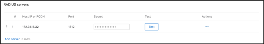
Radius integration (e.g. Cisco ISE)
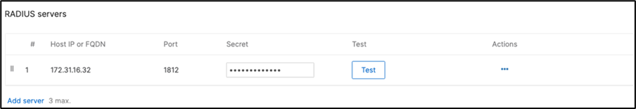
1. If using an external Radius server (e.g. Cisco ISE), then ensure that the network segment where ISE is hosted can access the Management VLAN configured on your network devices (or the Alternate Management Interface on MR and/or MS if configured and where applicable).
2. Ensure that all required ports are opened where applicable (e.g. 1812, 1813, etc.).
| Tech Tip: It is recommended to access the Radius server via VPN as the Radius traffic sourced from Meraki devices is not encrypted. |
1. If using an external identity source (e.g. Active Directory), then ensure that the network segment where the AD is hosted can access the Management VLAN configured on your network devices (or the Alternate Management Interface on MR and/or MS if configured with Radius integration).
2. Ensure that all required ports are opened where applicable (e.g. 3268, 389, etc.).
| Tech Tip: It is recommended to access the Active Directory server via VPN as the traffic is not encrypted (only port 3268 is supported). |
Catalyst onboarding for cloud monitoring (C9200/9300/9500)
For ease of management, Customers can onboard Cisco C9200/9300/9500 switches/stacks for Cloud Monitoring such that they can be available in the Meraki Dashboard in Monitor only mode. This process enables dashboard monitoring on these switches/stacks and selected configuration parameters will be visible in the Meraki Dashboard. Please refer to the following article for the supported Catalyst 9000 series.
Pre-requisites
Please ensure the following prior to onboarding a switch/stack for Cloud Monitoring:
● It is a supported model (Please refer to this article)
● Running IOS-XE 17.3 – 17.10.1
● It must have an SVI or routed interface that has access to the Internet on port TCP 443
● It must have a valid DNS server
● It must have a valid DNA software subscription
● It must have Telnet for connectivity pre-check (Please refer to this article)
● A valid Dashboard account and API Key
● A computer with both access to internet on port 443 and access to the switch(es)
| Tech Tips
● HTTPS proxies to access the API endpoint and the TLS gateway are not currently supported. If necessary, ensure rules are in place to allow direct HTTPS connections to each.
● Connectivity must be via a front-panel port (not the management interface).
● Only the default VRF is supported.
● Ensure routes are in place to reach external addresses including a default route (use of ip default-gateway is not supported).
● IP routing (ip routing) must be enabled on the switch or will be enabled as part of onboarding.
● Ensure DNS is enabled on the switch (ip name-server {DNS server IP} configured).
● Ensure DNS lookup is enabled (ip domain lookup).
● NTP needs to be enabled on the switch (ntp server {address}), and the switch clock must reflect the correct time.
● AAA on the switch must be configured using aaa new model.
● RADIUS authentication is not currently supported.
● SSH access to the switch CLI must be enabled and accessible via the computer used for onboarding.
● The user account for onboarding must have privilege-15 level access on the switch.
|
Onboarding catalyst devices for cloud monitoring
The onboarding process for the C9500 core switches is out of scope for the purposes of this CVD. Please refer to the following article for a step by step guide on onboarding Catalyst for Cloud Monitoring.
Switch Status on Meraki dashboard
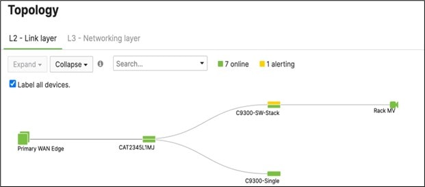
Once the device has been onboarded for Meraki dashboard monitoring, it should come online on dashboard after several minutes and also the network topology will show all switches in Monitor Only mode.
Design and configuration guidelines
Option 1: STP Based convergence with Native VLAN 1
Overview
This design option allows for flexibility in terms of VLAN and IP addressing across the Campus LAN such that the same VLAN can span across multiple access switches/stacks thanks to Spanning Tree that will ensure that you have a loop-free topology. However, this method of convergence is considered non- deterministic since the path of execution isn't fully determined (unlike Layer 3 routing protocols for example). As a result, convergence can be slow and STP must be tuned to provide best results.
This design is based on consistent STP protocols running in this campus deployment, as such Multiple Spanning Tree Protocol (MST, aka 802.1s) will be configured since it is supported on both the Meraki and Catalyst platforms.
| Tech Tip: It is recommended to run the same STP protocol across all switches (MST in this case). Running any other protocol on Catalyst (e.g. PVST) can introduce undesired behavior and can be more difficult to troubleshoot. |
You should consider this option if you need a consistent VLAN assignment across all switching closets. Here are some things to consider about this design option:
Pros:
● Flexibility in your VLAN design
● Facilitates Wireless Roaming across the whole campus
● Easier to deploy and consistent configuration across the entire Campus LAN
Cons:
● Non-deterministic route failover
● Slow convergence
● Different STP protocol support on Cloud Managed and Cloud Monitored Catalyst Switches
Since MST will be used as a loop prevention mechanism, all SVIs will be created on the collapsed core layer.
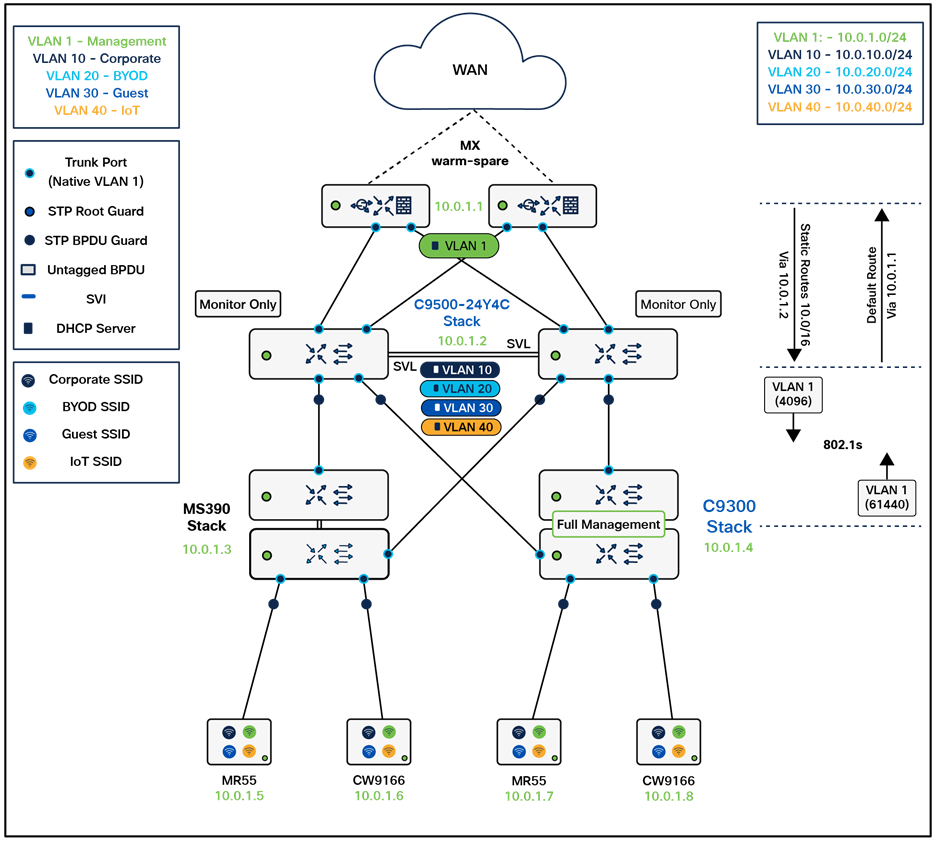
Logical architecture
The following diagram shows the logical architecture highlighting STP convergence within a campus LAN design leveraging Cloud Managed and Cloud Monitored Catalyst platforms:
Physical architecture
The following diagram shows the physical architecture and port list for this design:

Assumptions
The following assumptions have been considered:
● It is assumed that Wireless roaming is required everywhere in the Campus
● It is assumed that VLANs are spanning across multiple zones/closets
● Corporate SSID (Broadcast in all zones/areas) users are assigned VLAN 10 on all APs. CoA VLAN is VLAN 30 (via Cisco ISE)
● BYOD SSID (Broadcast in all zones/areas) users are assigned VLAN 20 on all APs. CoA VLAN is VLAN 30 (via Cisco ISE)
● Guest SSID (Broadcast in all zones/areas) users are assigned VLAN 30 on all APs
● IoT SSID (Broadcast in all zones/areas) users are assigned VLAN 40 on all APs
● Access Switches will be running in Layer 2 mode (No SVIs or DHCP)
● MS390 Access Switches physically stacked together
● C9300-M (or compatible) Access Switches physically stacked together
● C9500 Core Switches with Stackwise-virtual stacking using SVLs
● Access Switch uplinks are in trunk mode with native VLAN = VLAN 1 (Management VLAN*)
● STP root is at Distribution/Collapsed-core
● Distribution/Collapsed-core uplinks are in Trunk mode with Native VLAN = VLAN 1 (Management VLAN)
● All VLAN SVIs are hosted on the core layer
● Network devices will be assigned fixed IPs from the management VLAN DHCP pool. Default Gateway is 10.0.1.1
| Tech Tip: The client serving SVIs (offering DHCP services) were configured in this case on the C9500 Core Stack. However, it is also possible to configure them on the WAN Edge MX instead. In this case, please remember to configure the C9500 Core Stack uplinks AND the MX Downlinks with the appropriate VLANs in the Allowed VLAN list. |
| Tech Tip: While it is possible to configure a different Management VLAN than VLAN 1, the design and configuration guidelines in the coming section will assume that VLAN 1 is the Management VLAN. Please refer to this separate section should you wish to configure a different Management VLAN for your Campus LAN. |
Network segments
Please check the following table for more information about the network segments (e.g. VLANs, SVIs, etc.) for this design:
| Network Segment |
VLAN ID |
Subnet |
Default Gateway |
Notes |
| Management |
1 |
10.0.1.0/24 |
10.0.1.1 |
SVI hosted on edge MX |
| Corporate Devices (Wireless and Wired) |
10 |
10.0.10.0/24 |
10.0.10.1 |
SVI hosted on core switches |
| BYOD Wireless Devices |
20 |
10.0.20.0/24 |
10.0.20.1 |
SVI hosted on core switches |
| Guest Wireless Devices |
30 |
10.0.30.0/24 |
10.0.30.1 |
SVI hosted on core switches |
| IoT Wireless Devices |
40 |
10.0.40.0/24 |
10.0.40.1 |
SVI hosted on core switches |
| Tech Tip: Please size your subnets based on your own requirements. The above table is for illustration purposes only |
| Tech Tip: In this example, the Management VLAN has been created on the Edge MX. Alternatively, you can create the SVI on the C9500 Core Stack. |
| Application |
MR |
Access switches |
Core switches |
MX Appliance |
| SIP (Voice) |
EF DSCP 46 AC_Vo |
Trust incoming values DSCP 46 CoS 5 |
Trust incoming values |
EF DSCP 45 LLQ Unlimited |
| Webex and Skype |
AF41 DSCP 34 AC_VI |
Trust incoming values DSCP 34 CoS 4 |
Trust incoming values |
Af41 DSCP 34 High Priority |
| All Video and Music |
AF21 DSCP 18 AC_BE |
Trust incoming values DSCP 18 CoS 2 |
Trust incoming values |
AF21 DSCP 18 Medium Priority 5Mbps / Client |
| Software Updates |
AF11 DSCP 10 AC_BK |
Trust incoming values DSCP 10 CoS 1 |
Trust incoming values |
AF11 DSCP 10 |
Device list
| Device |
Name |
Management IP address |
Notes |
| MX250 |
Primary WAN Edge |
10.0.1.1 |
warm-spare |
| MX250 |
Spare WAN Edge |
||
| C9500-24YCY |
C9500-01 |
10.0.1.2 |
Stackwise Virtual (C9500-Core-Stack) |
| C9500-24CY |
C9500-02 |
||
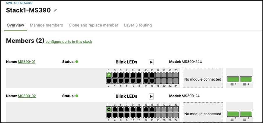
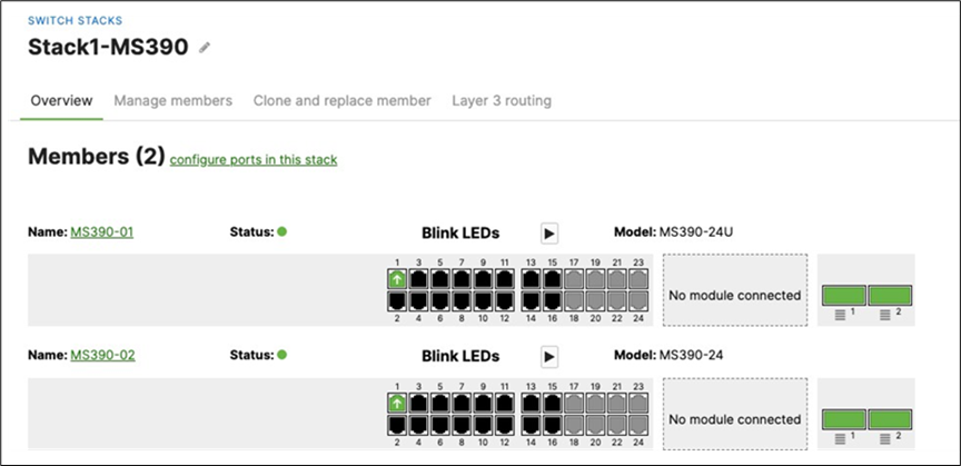
| MS390-24P |
MS390-01 |
10.0.1.3 |
Physical Stacking (Stack1-MS390) |
| MS390-24P |
MS390-02 |
||
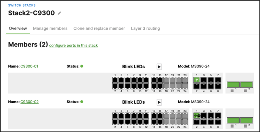
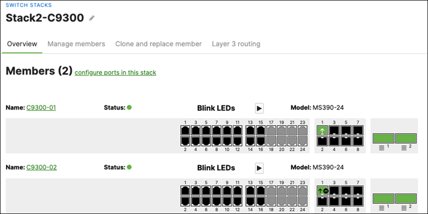
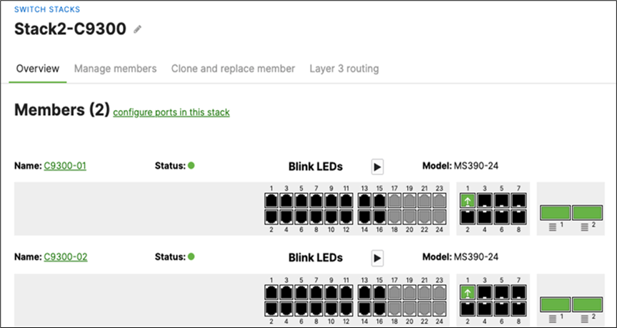
| C9300-24P |
C9300-01 |
100.1.4 |
Physical Stacking (Stack2-C9300) |
| C9300-24P |
C9300-02 |
||
| MR55 |
AP1_Zone1 |
10.0.1.5 |
Tag = Zone1 |
| C9166 (eq MR57) |
AP2_Zone1 |
10.0.1.6 |
Tag = Zone1 |
| MR55 |
AP3_Zone2 |
10.0.1.7 |
Tag = Zone2 |
| C9166 (eq MR57) |
AP4_Zone2 |
10.0.1.8 |
Tag = Zone2 |
Access policies
| Access Policy Name |
Purpose |
Configuration |
Notes |
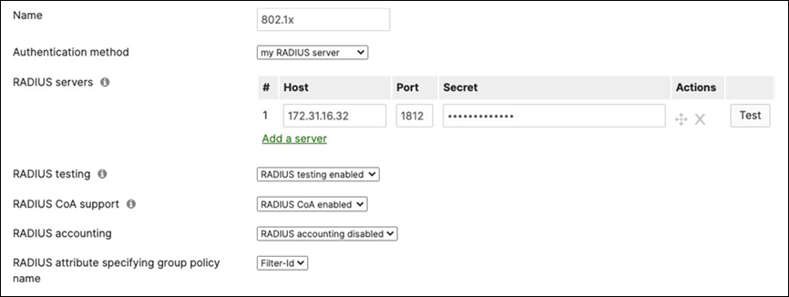
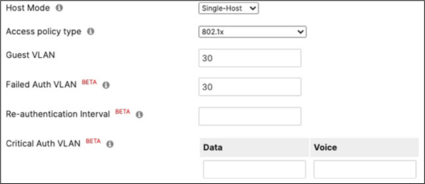
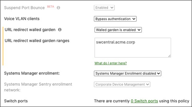
| Wired-1x |
802.1x Authentication via Cisco ISE for wired clients that support 802.1x |
Authentication method = my Radius server Radius CoA = enabled Host mode = Single-Host Access Policy type = 802.1x Guest VLAN = 30 Failed Auth VLAN = 30 Critical Auth VLAN = 30 Suspend Port Bounce = Enabled Voice Clients = Bypass authentication Walled Garden = enabled |
Cisco ISE authentication and posture checks |
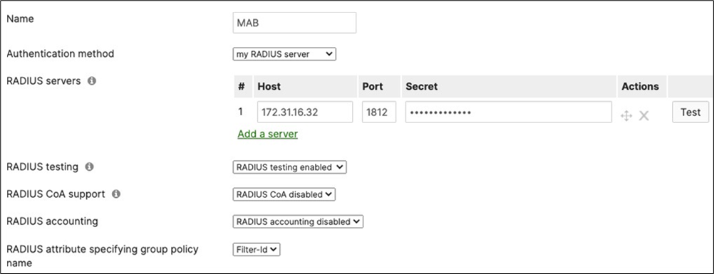
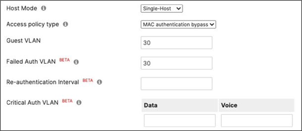
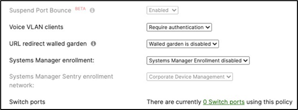
| Wired-MAB |
MAB Authentication via Cisco ISE for wired clients that do not support 802.1x |
Authentication method = my Radius server Radius CoA = disabled Host mode = Single-Host Access Policy type = MAC authentication bypass Guest VLAN = 30 Failed Auth VLAN = 30 Critical Auth VLAN = 30 Suspect Port Bounce = Enabled Voice Clients = Bypass authentication Walled Garden = disabled |
Cisco ISE authentication |
| Tech Tip: The above Access Policies are for illustration purposes only. Please configure your Access Policies as required. |
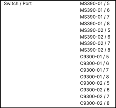
Port list
| Device name |
Port |
Far-end |
Port details |
Notes |
|||
| Primary WAN Edge / Spare WAN Edge |
1 |
WAN1 |
|
VIP1 |
|||
| Primary WAN Edge / Spare WAN Edge |
2 |
WAN2 |
|
VIP2 |
|||
| Primary WAN Edge |
19 |
9500-01 (Port Twe1/0/1) |
Trunk (Native VLAN 1) |
Downlink |
|||
| 20 |
9500-02 (Port Twe2/0/1) |
Trunk (Native VLAN 1) |
Downlink |
||||
| Spare WAN Edge |
19 |
9500-01 (port Twe1/0/2) |
Trunk (Native VLAN 1) |
Downlink |
|||
| 20 |
9500-02 (Port Twe2/0/2) |
Trunk (Native VLAN 1) |
Downlink |
||||
| 9500-01 |
Twe1/0/1 |
Primary WAN Edge (Port 19) |
switchport access vlan 1 auto qos trust dscp policy static sgt 2 trusted |
Uplink |
|||
| Twe1/0/2 |
Spare WAN Edge (Port 19) |
switchport access vlan 1 auto qos trust dscp policy static sgt 2 trusted |
Uplink |
||||
| 9500-02 |
Twe2/0/1 |
Primary WAN Edge (Port 20) |
switchport access vlan 1 auto qos trust dscp policy static sgt 2 trusted |
Uplink |
|||
| Twe2/0/2 |
Spare WAN Edge (Port 20) |
switchport access vlan 1 auto qos trust dscp policy static sgt 2 trusted |
Uplink |
||||
| 9500-01 |
Twe1/0/23 |
MS390-01 (Port 1) |
switchport trunk native vlan 1 switchport trunk allowed vlans 1,10,20,30,40 channel-group 1 mode active spanning-tree guard root auto qos trust dscp policy static sgt 2 trusted |
Downlink |
|||
| Twe1/0/24 |
C9300-01 (Port 1) |
switchport trunk native vlan 1 switchport trunk allowed vlans 1,10,20,30,40 channel-group 2 mode active spanning-tree guard root auto qos trust dscp policy static sgt 2 trusted |
Downlink |
||||
| 9500-02 |
Twe2/0/23 |
MS390-02 (Port 1) |
switchport trunk native vlan 1 switchport trunk allowed vlans 1,10,20,30,40 channel-group 1 mode active spanning-tree guard root auto qos trust dscp policy static sgt 2 trusted |
Downlink |
|||
| Twe2/0/24 |
C9300-02 (Port 1) |
switchport trunk native vlan 1 switchport trunk allowed vlans 1,10,20,30,40 channel0group 2 mode active spanning-tree guard root auto qos trust dscp policy static sgt 2 trusted |
Downlink |
||||
| 9500-01 |
Hu1/0/25 |
C9500-02 (Port Hu2/0/26) |
stackwise-virtual link 1 |
Stackwise Virtual |
|||
| Hu1/0/26 |
C9500-02 (Port Hu2/0/25) |
stackwise-virtual link 1 |
Stackwise Virtual |
||||
| 9500-02 |
Hu2/0/25 |
C9500-01 (Port Hu1/0/26) |
stackwise-virtual link 1 |
Stackwise Virtual |
|||
| Hu2/0/26 |
C9500-01 (PortHu1/0/25) |
stackwise-virtual link 1 |
Stackwise Virtual |
||||
| MS390-01 |
5-8 |
Wired Clients |
Access (Data VLAN 1) Access Policy = Wired-1x PoE Enabled STP BPDU Guard Tag = Wired Clients 802.1x AdP: Corp |
For wired clients supporting 802.1x |
|||
| MS390-02 |
|||||||
| C9300-01 |
|||||||
| C9300-02 |
|||||||
| MS390-01 |
9-12 |
Wired Clients |
Access (Data VLAN 1) Access Policy = MAB PoE Enabled STP BPDU Guard Tag = Wired Clients MAB AdP: Corp |
For wired clients that do not support 802.1x |
|||
| MS390-02 |
|||||||
| C9300-01 |
|||||||
| C9300-02 |
|||||||
| MS390-01 |
13-16 |
MR |
Trunk (Native VLAN 1) PoE Enabled STP BPDU Guard Tag = MR WLAN Peer SGT Capable AdP: Infrastructure |
Allowed VLANs: 1,10,20,30,40 |
|||
| MS390-02 |
|||||||
| C9300-01 |
|||||||
| C9300-02 |
|||||||
| MS390-01 |
1 |
9500-01 (Port Twe1/0/23) |
Trunk (Native VLAN 1)PoE Disabled Name: Core 1 Tag = Uplink Peer SGT Capable AdP: Infrastructure |
Allowed VLANs: 1,10,20,30,40 |
|||
| MS390-02 |
1 |
9500-02 (Port Twe2/0/23) |
Trunk (Native VLAN 1) PoE Disabled Name: Core 2 Tag = Uplink Peer SGT Capable AdP: Infrastructure |
Allowed VLANs: 1,10,20,30,40 |
|||
| C9300-01 |
C9300-01 / C9300-NM-8X / 1 |
9500-01 (Port Twe1/0/24) |
Trunk (Native VLAN 1) PoE Disabled Name: Core 1 Tag = Uplink Peer SGT Capable AdP: Infrastructure |
Allowed VLANs: 1,10,20,30,40 |
|||
| C9300-02 |
C9300-02 / C9300-NM-8X / 1 |
C9500-02 (Port Twe2/0/24) |
Trunk (Native VLAN 1) PoE Disabled Name: Core 2 Tag = Uplink Peer SGT Capable AdP: Infrastructure |
Allowed VLANs: 1,10,20,30,40 |
|||
Wireless SSID list
| SSID Name |
Broadcast |
Configuration |
Notes |
Firewall and Traffic Shaping |
|||||
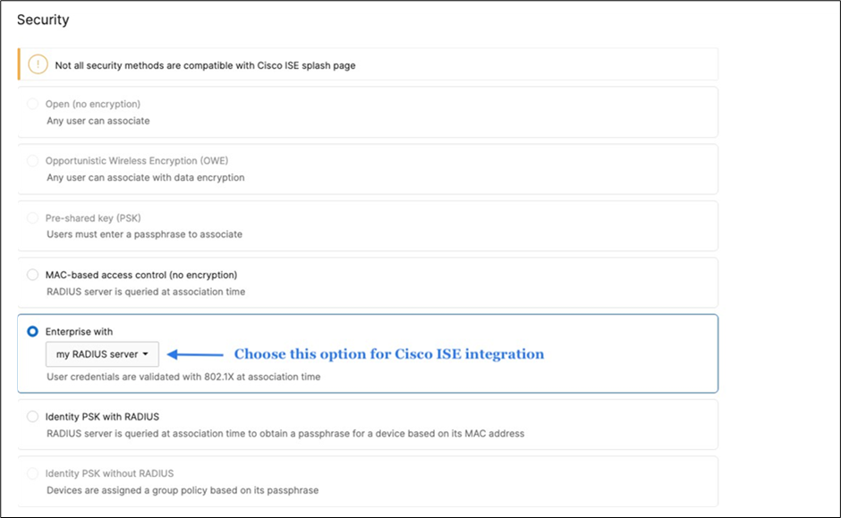
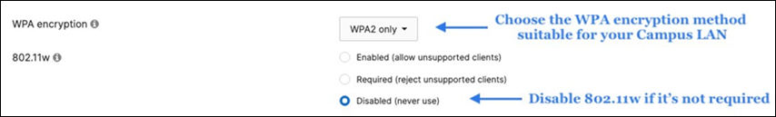
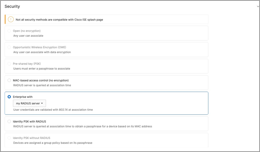
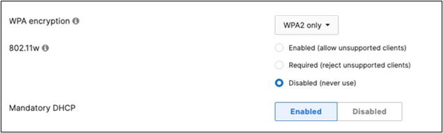
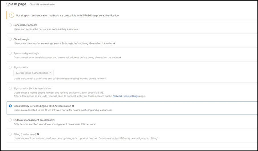
| Acme Corp |
All APs |
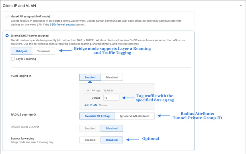
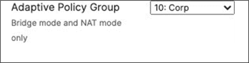
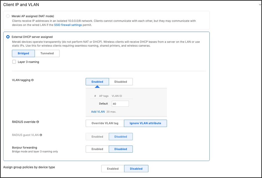
Association = Enterprise with my Radius server Encryption = WPA2 only Splash Page = Cisco ISE Radius CoA = Enabled SSID mode = Bridge mode VLAN Tagging = 10 (ISE Override) AdP Group = 10:Corp Radius override = Enabled Mandatory DHCP = Enabled Layer 2 isolation = Disabled Allow Clients access LAN = Allow Traffic Shaping = Enabled with default settings |
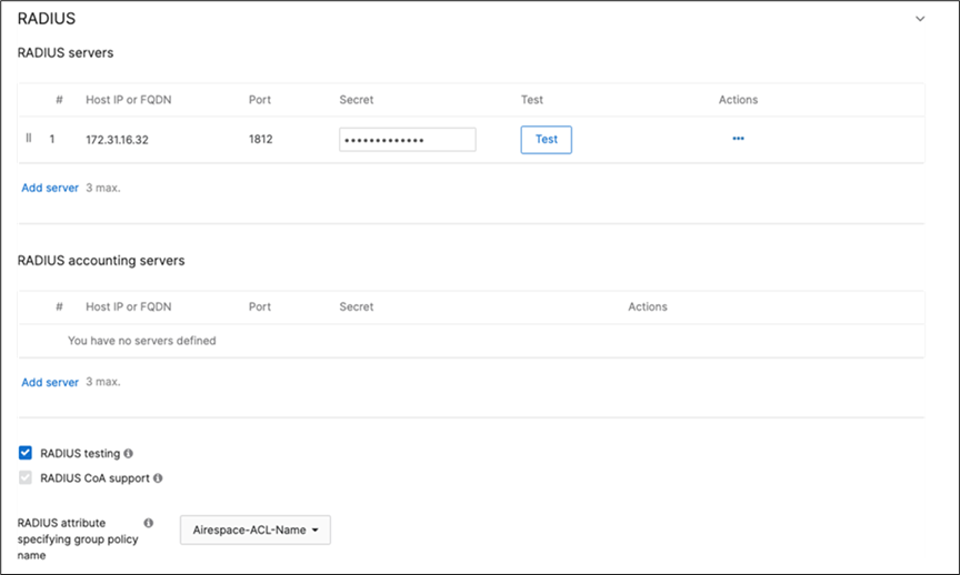
Cisco ISE Authentication and posture checks (172.31.16.32/1812) |
Layer 2 Isolation = Disabled Allow Access to LAN = Enabled Per-Client Bandwidth Limit = 50Mbps Per-SSID Bandwidth Limit = Unlimited Enable Default Traffic Shaping rules SIP - EF (DSCP 46) Software Updates - AF11 (DSCP 10) Webex and Skype - AF41 (DSCP 34) All Video and Music - AF21 (DSCP 18) |
|||||
| Acme BYOD |
All APs |
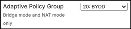
Association = Enterprise with my Radius server Encryption = WPA2 only 802.11w = Enabled Splash Page = Cisco ISE SSID mode = Bridge mode VLAN Tagging = 20 AdP Group = 20:BYOD Radius override = Disabled Mandatory DHCP = Enabled Layer 2 isolation = Disabled Allow Clients access LAN = Allow Traffic Shaping = Enabled with default settings |
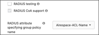
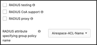
Cisco ISE Authentication (via Azure AD) and posture checks. Dynamic GP assignment (Radius attribute = Airospace-ACLNAME) |
Layer 2 Isolation = Disabled Allow Access to LAN = Enabled Per-Client Bandwidth Limit = 50Mbps Per-SSID Bandwidth Limit = Unlimited Enable Default Traffic Shaping rules SIP - EF (DSCP 46) Software Updates - AF11 (DSCP 10) Webex and Skype - AF41 (DSCP 34) All Video and Music - AF21 (DSCP 18) |
|||||
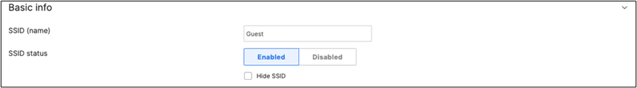
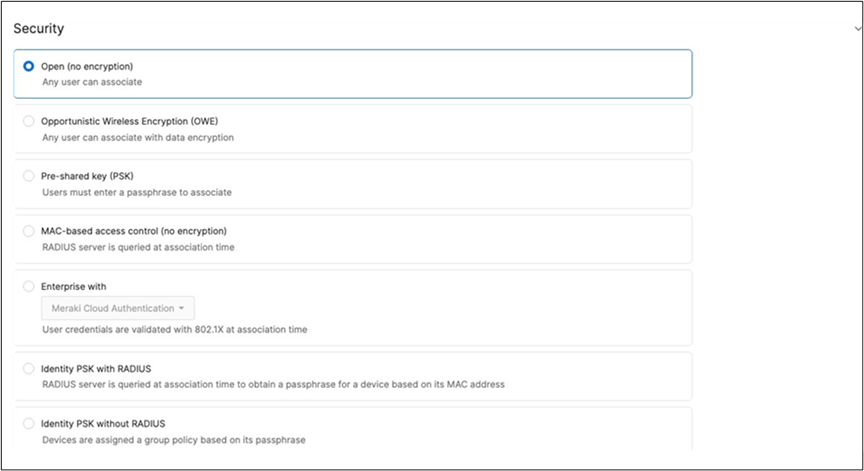
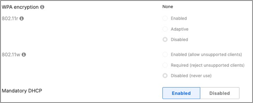
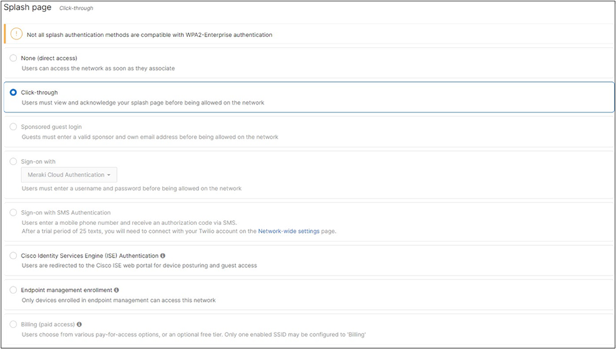
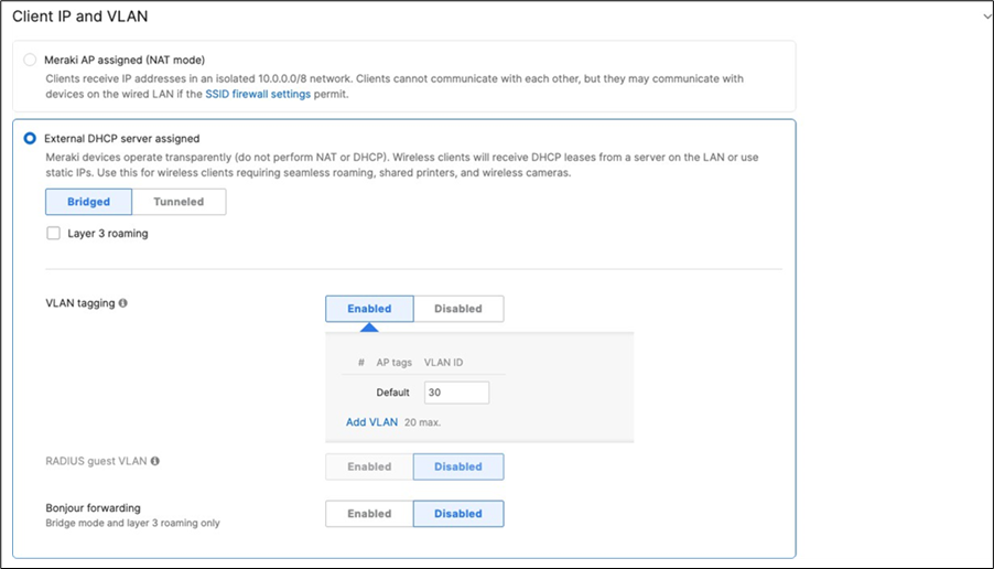
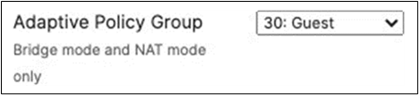
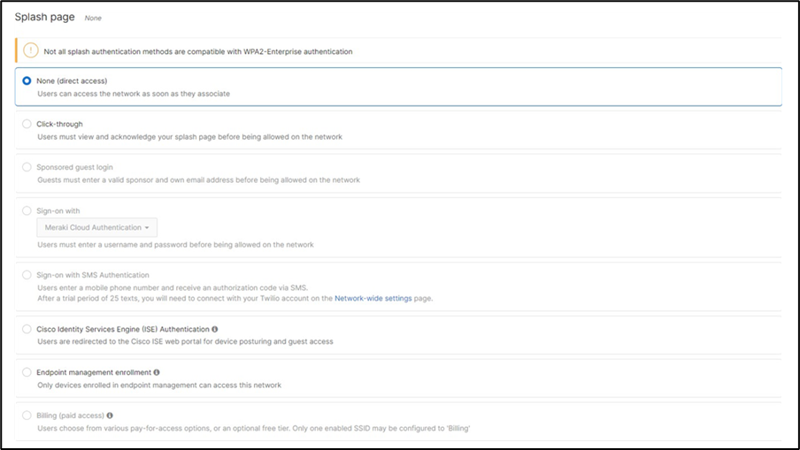
| Guest |
All APs |
802.11w = Enabled Splash Page = Click-Through SSID mode = Bridge mode VLAN Tagging = 30 AdP Group = 30:Guest Radius override = Disabled Mandatory DHCP = Enabled Layer 2 isolation = Enabled Allow Clients access LAN = Deny Per SSID limit = 100Mbps Traffic Shaping = Enabled with default settings |
Meraki Authentication |
Layer 2 Isolation = Enabled Allow Access to LAN = Disabled Per-Client Bandwidth Limit = 5Mbps Per-SSID Bandwidth Limit = 100Mbps Enable Default Traffic Shaping rules SIP - EF (DSCP 46) Software Updates - AF11 (DSCP 10) Webex and Skype - AF41 (DSCP 34) All Video and Music - AF21 (DSCP 18) |
|||||
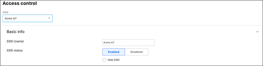
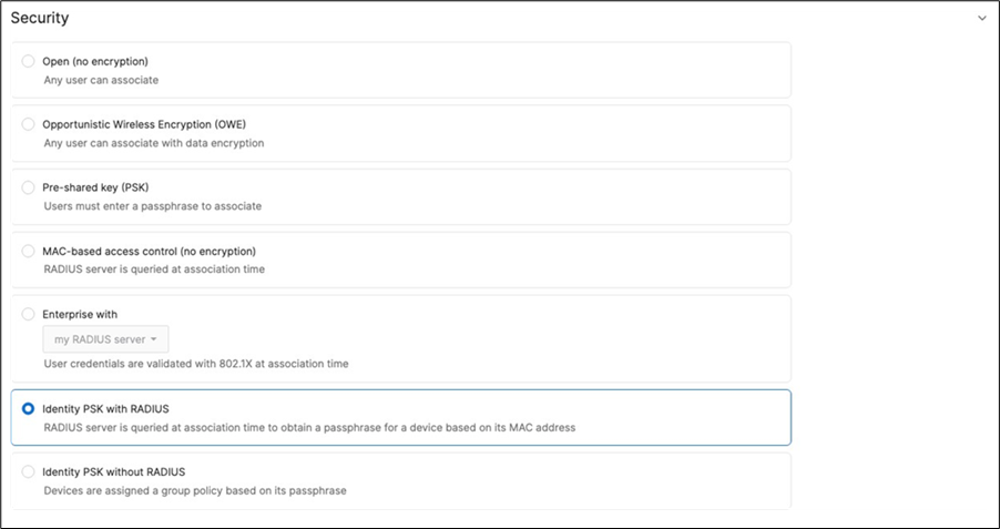
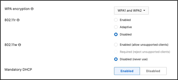
| Acme IoT |
All APs |
Association = identity PSK with Radius Encryption = WPA1 and WPA2 802.11r = Disabled 802.11w = Disabled Splash Page = None Radius CoA = Disabled SSID mode = Bridge mode VLAN Tagging = 40 AdP Group = 40:IoT Radius override = Disabled Mandatory DHCP = Enabled Allow Clients access LAN = Deny Per SSID limit = 10Mbps Traffic Shaping = Enabled with default settings |
Cisco ISE is queried at association time to obtain a passphrase for a device based on its MAC address. Dynamic GP assignment (Radius attribute Filter-Id) |
Layer 2 Isolation = Disabled Allow Access to LAN = Enabled Per-Client Bandwidth Limit = 5Mbps Per-SSID Bandwidth Limit = Unlimited Enable Default Traffic Shaping rules SIP - EF (DSCP 46) Software Updates - AF11 (DSCP 10) Webex and Skype - AF41 (DSCP 34) All Video and Music - AF21 (DSCP 18) |
| Tech Tips:
● The above configuration is for illustration purposes only. Please configure your SSIDs based on your own requirements (
mode, IP assignment,
traffic
shaping, etc.)
● Please note that Adaptive Policy on MR requires MR-ADV license. For more information about the requirements, please refer to this
document.
|
Group policies
| Group Policy Name |
Purpose |
Configuration | Notes |
| BYOD |
For BYOD users to limit bandwidth per client and restrict access as desired. GP will be dynamically assigned based on Radius attribute |
Name = BYOD Schedule = disabled Bandwidth = 10Mbps Firewall and Traffic Shaping = None Layer 3 FW = None Layer 7 FW = Block All Email VLAN = 20 Splash = N/A |
| Tech Tip: The above Group Policies are for illustration purposes only. Please configure your Group Policies as required. To configure your Radius server to assign a dynamic Group Policy please refer to this article. |
Configuration and implementation guidelines
| Notes:
● It is assumed that by this stage, Catalyst devices have been added to dashboard for either Monitoring (e.g. C9500) or Management (e.g. C9300). For more information, please refer to the above section.
● Before proceeding, please make sure that you have the appropriate licenses claimed into your dashboard account.
|
1. Login to your dashboard account (or create an account if you don't have one)
2. Navigate to Organization > Configure > Inventory
3. For Co-term license model, click on Claim. And for PDL, please click on Add

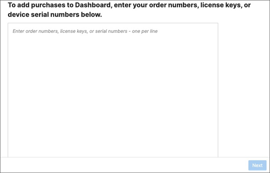
4. Enter the order and/or serial number(s) to claim the devices into your account. For PDL, click Next then please choose to add them to Inventory (Do not add them to a network)
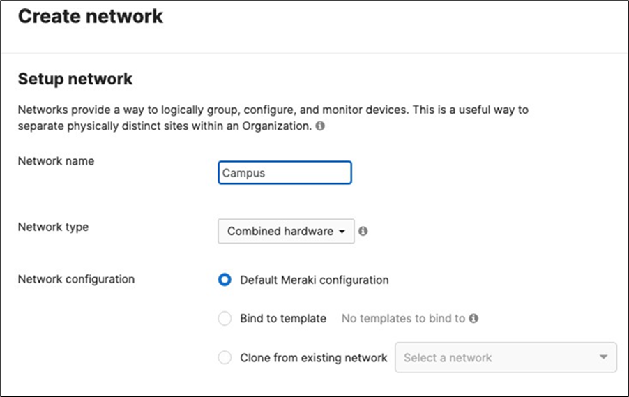
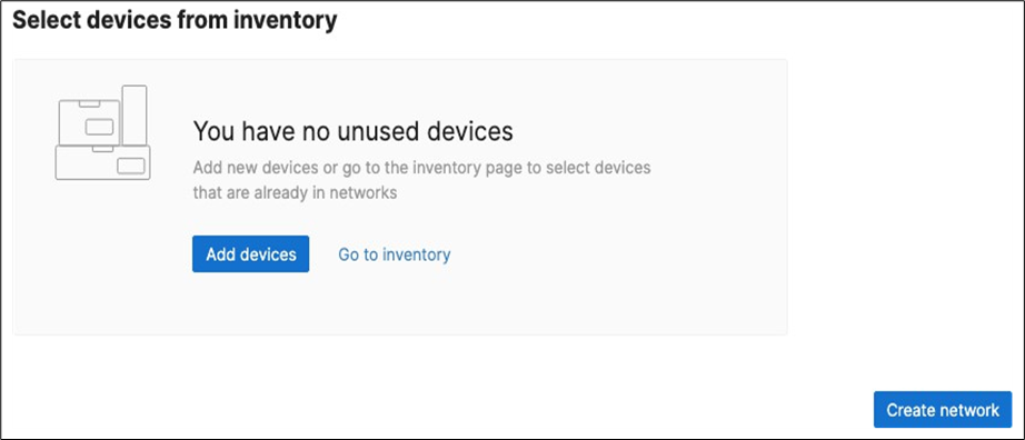
5. Create a Dashboard Network: Navigate to Organization > Configure > Create network to create a network for your Campus LAN (Or use an existing network if you already have one). If you are creating a new network, please choose "Combined" as this will facilitate a single topology diagram for your Campus LAN. Choose a name (e.g. Campus) and then click Create network
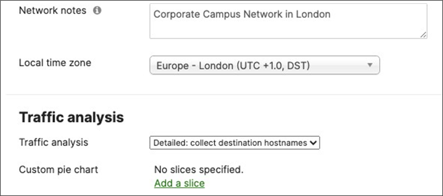
6. Dashboard Network Settings: Navigate to Network-wide > Configure > General and choose the settings for your network (e.g. Time zone, Traffic Analytics, firmware upgrade day/time, etc.)
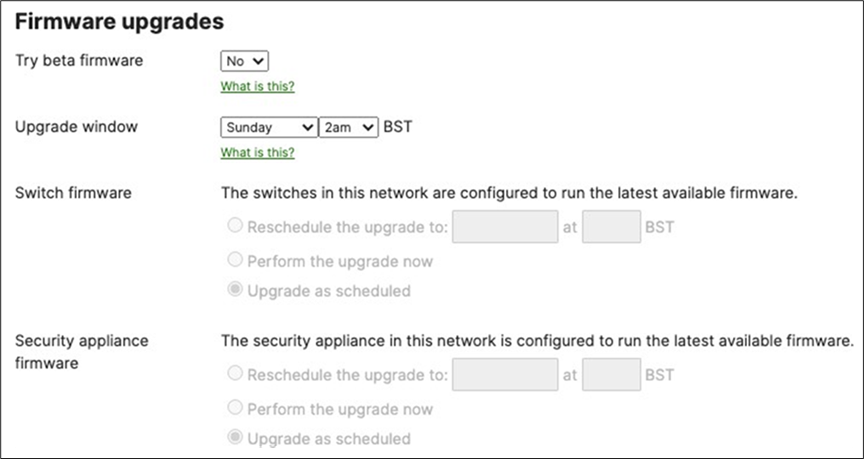
7. Schedule Firmware Upgrade: Navigate to Organization > Monitor > Firmware upgrades to select the firmware settings for your devices such that devices upgrade once they connect to dashboard. Select the device type then click on Schedule upgrade.
8. Add Devices to a Dashboard Network: Navigate to Organization > Configure > Inventory:
● For Co-term licensing model, select the MS390 and C9300 switches and the Primary WAN Edge then click on Add then choose the Network Campus
● For PDL licensing model, select the MS390 and C9300 switches and the Primary WAN Edge then click on Change network assignment and then choose the Network Campus
● Please DO NOT add the Secondary WAN Edge device at this stage
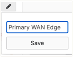
9. Rename MX Security Appliance: Navigate to Security and SD-WAN > Monitor > Appliance status then click on the edit button to rename the MX to Primary WAN Edge then click on Save.
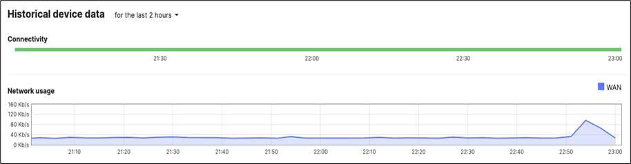
10. MX Connectivity: Plug in your WAN uplink(s) on the Primary WAN Edge MX then power it on and wait for it to come online on dashboard. This might take a few minutes as the MX will download its firmware and configuration. Navigate to Security and SD-WAN > Monitor > Appliance status and verify that the MX has come online and that its firmware and configuration is up to date.
11. Rename Access Switches: Navigate to Switching > Monitor > Switches then click on each MS390 and C9300 switch and then click on the edit button on top of the page to rename it per the above table then click on Save such that all your switches have their designated names.
12. Rename MR APs: Navigate to Wireless > Monitor > Access points then click on each AP and then click on the edit button on top of the page to rename it per the above table then click on Save such that all your APs have their designated names.
13. MR AP Tags: Navigate to Wireless > Monitor >Access points then click on each AP and then click on the edit button next to TAGS to add Tags to your AP per the above table then click on Save such that all your APs have their designated tags.

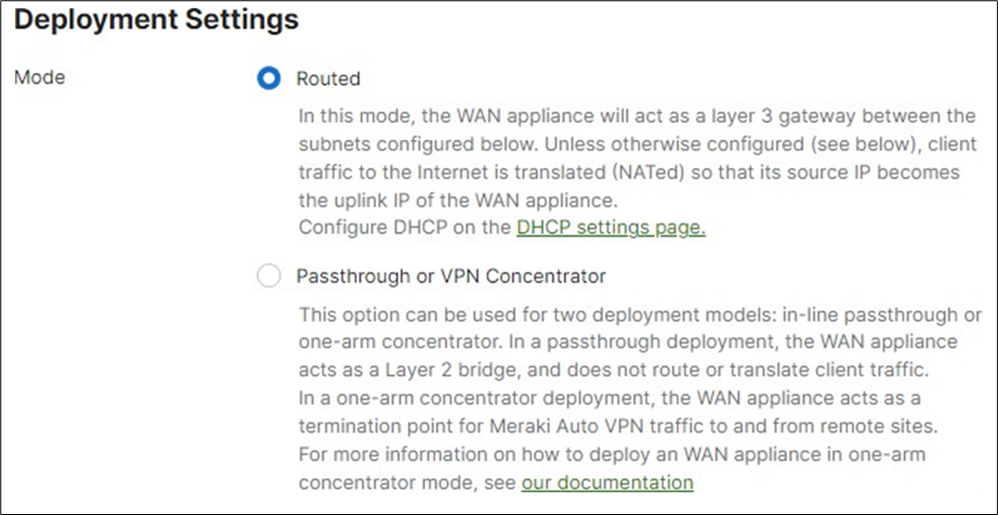
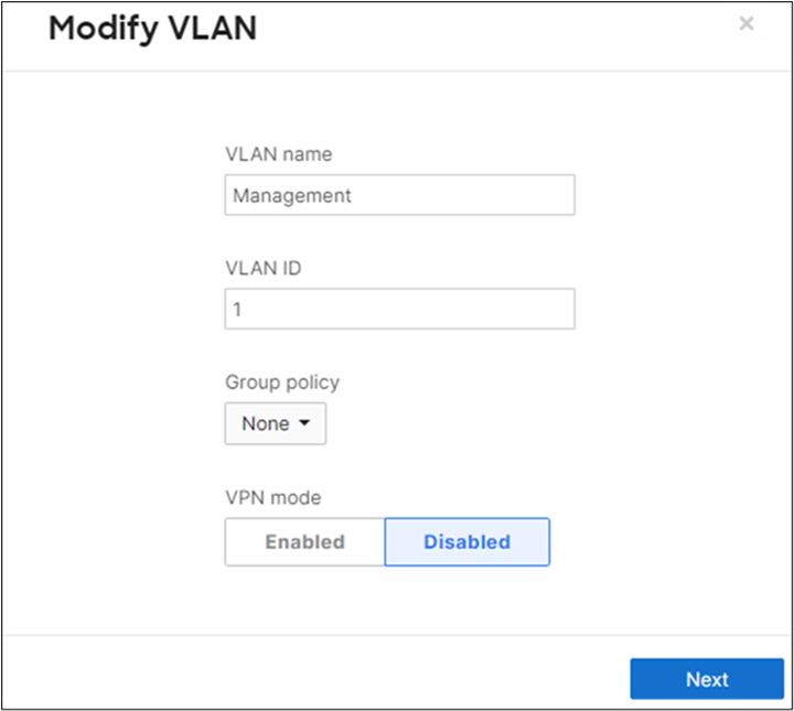
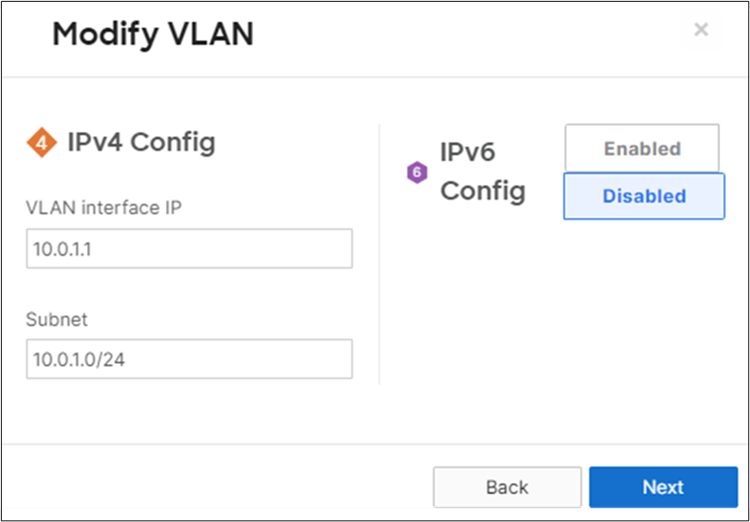
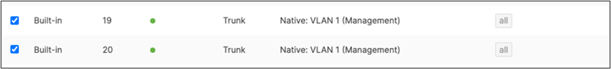
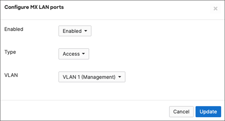
14. MX Addressing and VLANs: Navigate to Security and SD-WAN > Configure > Addressing and VLANs, and in the Deployment Settings menu select Routed mode. Further down the page on the Routing menu, click on VLANs then click on Add VLAN to add your management VLAN then click on Create. Then for the per-port VLAN settings, select your downlink ports (19 and 20) and click on Edit and configure them as access with VLAN 1 and click on Update. Finally, click on Save at the bottom of the page.
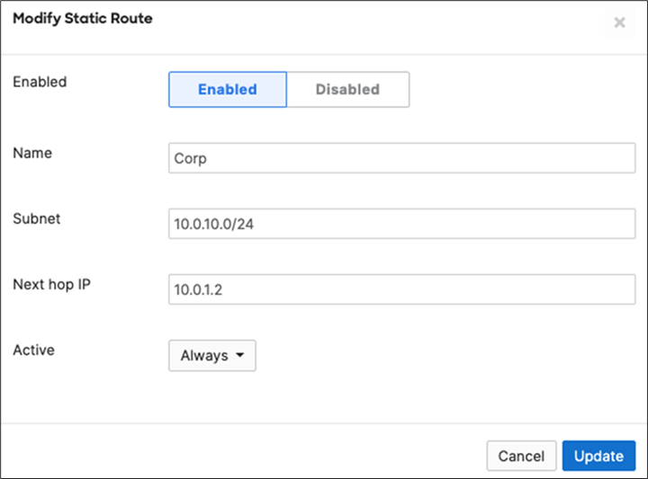
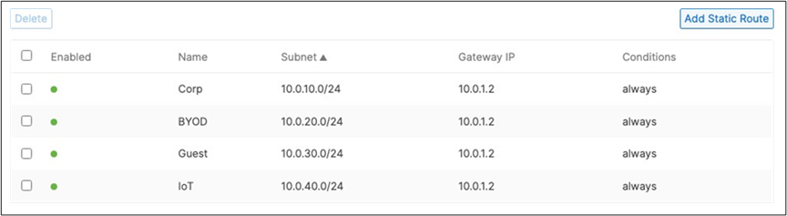
15. Campus LAN Static Routes: Create Static Routes for your Campus network by navigating further down the page to Static routes then click on Add Static Route. Start by adding your Corporate LAN subnet then click on Update and then add static routes to all other subnets (e.g. BYOD, Guest and IoT). Finally, click on Save at the bottom of the page. (The Next hop IP that you have used here will be used to create a fixed assignment for the Core Stack later in DHCP settings).
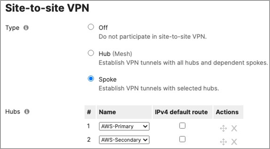
16. Optional - If you are accessing any resources over Meraki SD-WAN, please navigate to Security and SD-WAN > Configure > Site-to-site VPN and enable VPN based on your topology and traffic flow requirements. (In this case we will configure this Campus as Spoke with Split Tunneling)
● Choose Type: Spoke then click on Add a hub and select your hub site where you need access to resources via VPN. You can also add multiple hubs for resiliency. To choose Split Tunneling, please leave the box next to the Hub unticked as shown below.
● Under VPN Settings, choose which subnet to be Enabled in VPN (e.g. Management VLAN will be required for Radius authentication purposes as the MR/MS390/C9300 devices will reach out to Cisco ISE using their management IP). Any Subnet that needs to access resources via VPN must be Enabled otherwise keep it as Disabled.
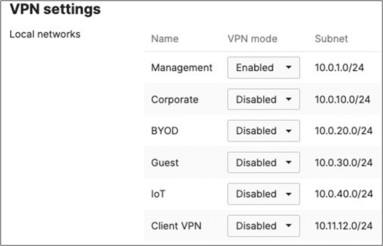
● Finally, click on Save at the bottom of the page
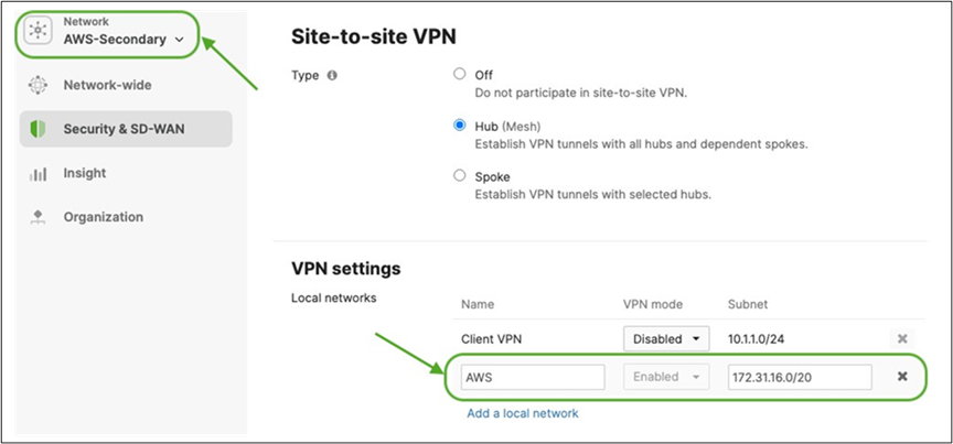
● On the Hub site, please make sure to advertise the subnets that are required to be reachable via VPN. Navigate to Security and SD-WAN > Configure > Site-to-site VPN then add a local network then click Save at the bottom of the page (Please make sure that you are configuring this on the Hub's dashboard network)
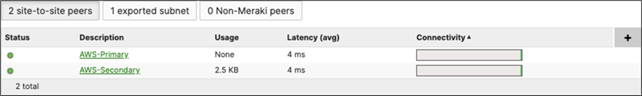
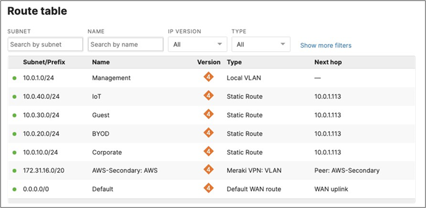
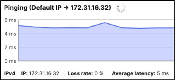
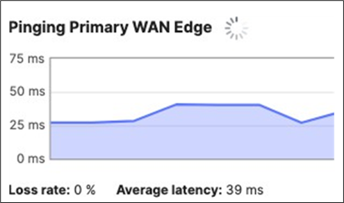
17. Optional - Verify that your VPN has come up by selecting your Campus LAN dashboard network from the Top-Left Network drop down list and then navigate to Security and SD-WAN > Monitor >VPN status then check the status of your VPN peers. Next, navigate to Security and SD-WAN > Monitor > Route table and check the status of your remote subnets that are reachable via VPN. You can also verify connectivity by pinging a remote subnet(e.g. 172.31.16.32 which is Cisco ISE) by navigating to Security and SD-WAN > Monitor > Appliance status then click on Tools and ping the specified IP address (Please note that the MX will choose the highest IP participating in VPN by default as the source).
Please note that in order to ping a remote subnet, you must either have BGP enabled or have static routes at the far-end pointing back to the Campus LAN local subnets.
In this example, the VPC in AWS has been configured with a Route Entry to route 10.0.1.0/24 via the vMX deployed in AWS that has a VPN tunnel back to the Campus LAN site.
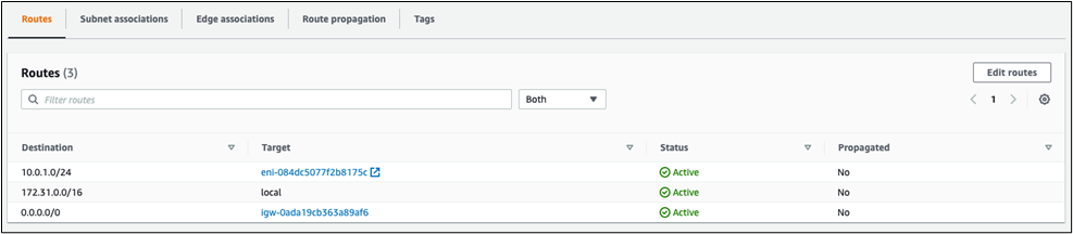
If the remote VPN peer (e.g. AWS) is configured in Routed mode, the static route is not required since traffic will always be NAT'd to a local reachable IP address.
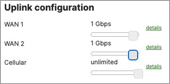
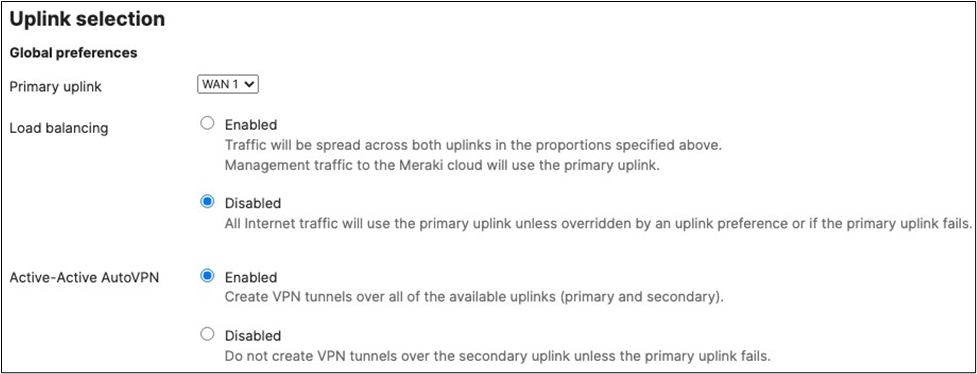
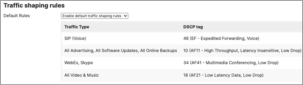
18. SD-WAN and Traffic Shaping Configuration: To configure Traffic Shaping settings for your Campus LAN site. Navigate to Security and SD-WAN > Configure > SD-WAN and Traffic Shaping to configure your preferred settings. For the purpose of this CVD, the default traffic shaping rules will be used to mark traffic with a DSCP tag without policing egress traffic (except for traffic marked with DSCP 46) or applying any traffic limits. (Please adjust these settings based on your requirements such as traffic limits or priority queue values. For more information about traffic shaping settings on the MX devices, please refer to the following article).
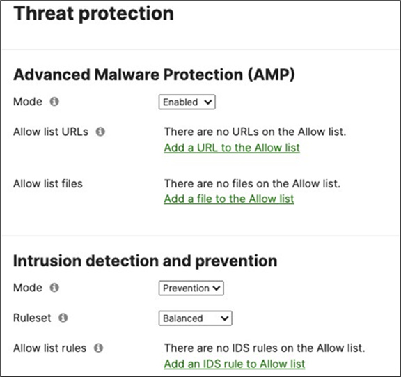
19. Optional - Configure Threat Protection (Requires Advanced License or above) for your Campus LAN site. Navigate to Security and SD-WAN > Configure > Threat Protection and choose the settings that meet your site requirements. Please see the following configuration example:
20. Click on Save at the bottom of the page.
21. Optional - Configure Content Filtering Settings (Requires Advanced License or above) for your Campus LAN site. Navigate to Security and SD-WAN > Configure > Content filtering and choose the settings that meet your site requirements. Please see the following configuration example:

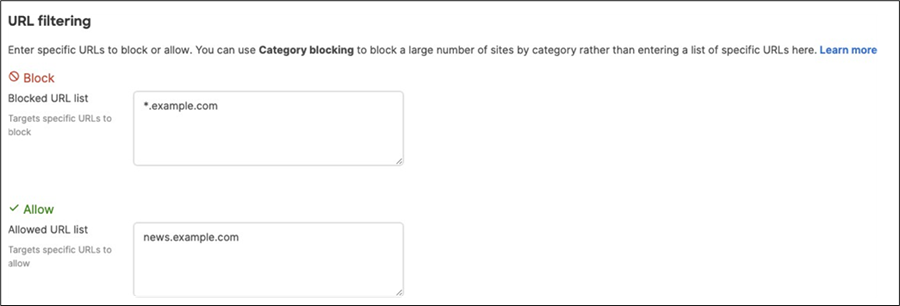
22. Click on Save at the bottom of the page.
23. Core Switch Uplinks: On the Catalyst 9500 core switches, Connect their uplinks to the Primary WAN Edge MX and power them both on.
24. Core Switch Network Access: Connect to first C9500 switch via console and configure it with the following commands:
| Switch#conft Enter configuration commands, one per line. End with CNTL/Z. Switch(config)#hostname 9500-01 9500-01(config)#ip domain name meraki-cvd.local 9500-01(config)#cdp run 9500-01(config)#lldp run 9500-01(config)#stackwise Please reload the switch for Stackwise Virtual configuration to take effect Upon reboot, the config will be part of running config but not part of start-up config. 9500-01(config-stackwise-virtual)#domain 1 9500-01(config)#exit 9500-01(config)#interface Twe1/0/1 9500-01(config-if)#switchport mode access 9500-01(config-if)#switchport access vlan 1 9500-01(config-if)#no shut 9500-01(config-if)#exit 9500-01(config)#interface Twe1/0/2 9500-01(config-if)#switchport mode access 9500-01(config-if)#switchport access vlan 1 9500-01(config-if)#no shut 9500-01(config-if)#exit 9500-01(config)#interface vlan 1 9500-01(config-if)#ip address dhcp 9500-01(config-if)#no shut 9500-01(config-if)#end 9500-01# 9500-01#sh ip int brief Interface IP-Address OK? Method Status Protocol Vlan1 10.0.1.110 YES DHCP up up GigabitEthernet0/0 unassigned YES NVRAM down down TwentyFiveGigE1/0/1 unassigned YES unset up TwentyFiveGigE1/0/2 unassigned YES unset up 9500-01#ping 8.8.8.8 Type escape sequence to abort. Sending 5, 100-byte ICMP Echos to 8.8.8.8, timeout is 2 seconds: !!!!! Success rate is 100 percent (5/5), round-trip min/avg/max = 4/4/5 ms 9500-01#ping cisco.com Type escape sequence to abort. Sending 5, 100-byte ICMP Echos to 72.163.4.185, timeout is 2 seconds: !!!!! Success rate is 100 percent (5/5), round-trip min/avg/max = 109/109/109 ms 9500-01#switch 1 renumber 1 9500-01#switch priority 5 9500-01#wr mem Building configuration... [OK] |
25. Core Switch Network Access: Connect to the second C9500 switch via console and configure it with the following commands:
| Switch>en Switch#conf t Enter configuration commands, one per line. End with CNTL/Z. Switch(config)#hostname 9500-02 9500-02(config)#ip domain name meraki-cvd.local 9500-01(config)#cdp run 9500-01(config)#lldp run 9500-02(config)#stackwise Please reload the switch for Stackwise Virtual configuration to take effect Upon reboot, the config will be part of running config but not part of start-up config. 9500-02(config-stackwise-virtual)#domain 1 9500-02(config)#exit 9500-02(config)#interface Twe1/0/1 9500-01(config-if)#switchport mode access 9500-02(config-if)#switchport access vlan 1 9500-02(config-if)#no shut 9500-02(config-if)#exit 9500-02(config)#interface Twe1/0/2 9500-01(config-if)#switchport mode access 9500-02(config-if)#switchport access vlan 1 9500-02(config-if)#no shut 9500-02(config-if)#exit 9500-02(config)#interface vlan 1 9500-02(config-if)#ip address dhcp 9500-02(config-if)#no shut 9500-02(config-if)#end 9500-02# 9500-02#sh ip int brief Interface IP-Address OK? Method Status Protocol Vlan1 10.0.1.111 YES DHCP up up GigabitEthernet0/0 unassigned YES NVRAM down down TwentyFiveGigE1/0/1 unassigned YES unset up up TwentyFiveGigE1/0/2 unassigned YES unset up up 9500-02#ping 8.8.8.8 Type escape sequence to abort. Sending 5, 100-byte ICMP Echos to 8.8.8.8, timeout is 2 seconds: !!!!! Success rate is 100 percent (5/5), round-trip min/avg/max = 4/4/5 ms 9500-02#ping cisco.com Type escape sequence to abort. Sending 5, 100-byte ICMP Echos to 72.163.4.185, timeout is 2 seconds: !!!!! Success rate is 100 percent (5/5), round-trip min/avg/max = 109/109/109 ms 9500-02#switch 1 renumber 2 9500-02#switch priority 1 9500-02#wr mem Building configuration... [OK] |
26. SVL Configuration: Now that both C9500 switches have access to the network, proceed to configure the Stackwise Virtual Links per the port list provided above (In this case with using two ports as part of the SVL providing a total stacking bandwidth of 80 Gbps).
| 9500-01(config)#interface HundredGigE1/0/25 9500-01(config-if)#stackwise-virtual link 1 9500-01(config-if)#no shut 9500-01(config-if)#exit 9500-01(config)#interface HundredGigE1/0/26 9500-01(config-if)#stackwise-virtual link 1 9500-01(config-if)#no shut 9500-01(config-if)#end 9500-01#wr mem Building configuration... [OK] 9500-01#reload Proceed with reload? [confirm] |
| 9500-02(config)#interface HundredGigE1/0/25 9500-02(config-if)#stackwise-virtual link 1 9500-02(config-if)#no shut 9500-02(config-if)#exit 9500-02(config)#interface HundredGigE1/0/26 9500-02(config-if)#stackwise-virtual link 1 9500-02(config-if)#no shut 9500-02(config-if)#end 9500-02#wr mem Building configuration... [OK] 9500-02#reload Proceed with reload? [confirm] |
27. Connect Stacking Cables: Whilst the C9500 switches are reloading, connect the stacking cables on both switches.
28. Verify Stackwise Configuration: Please wait for about 10 minutes for the switches to come back up and initialize the stack. Then, connect to the 9500-01 (Stack Master) via console to verify that the stack is operational. The stackwise-virtual link should be U (Up) and R (Ready).
| 9500-01#show stackwise-virtual Stackwise Virtual Configuration: ---------------------------- Stackwise Virtual : Enabled Domain Number : 1
Switch Stackwise Virtual Link Ports ----------------------------- 1 1 HundredGigE1/0/25 HundredGigE1/0/26 2 1 HundredGigE2/0/25 HundredGigE2/0/26 9500-01# 9500-01#show stackwise-virtual link Stackwise Virtual Link(SVL) Information: ----------------------------- Flags: ----- Link Status ----------- U-Up D-Down Protocol Status ----------- S-Suspended P-Pending E-Error T-Timeout R-Ready ----------------------------- Switch SVL Ports Link-Status Protocol-Status ------------------------------------------------ 1 1 HundredGigE1/0/25 U R HundredGigE1/0/26 U R 2 1 HundredGigE2/0/25 U R HundredGigE2/0/26 U R
9500-01# 9500-01#show stackwise-virtual bandwidth Switch Bandwidth ---------------- 1 80G 2 80G
9500-01# 9500-01#sh switch Switch/Stack Mac Address : b0c5.3c60.fba0 - Local Mac Address Mac persistency wait time: Indefinite H/W Current Switch# Role Mac Address Priority Version State *1 Active b0c5.3c60.fba0 5 V02 Ready 2 Standby 40b5.c111.01e0 1 V02 Ready
9500-01# |
29. Optional - Attach and configure stackwise-virtual dual-active-detection: DAD is a feature used to avoid a dual- active situation within a stack of switches. It will rely on a direct attachment link between the two switches to send hello packets and determine if the active switch is responding or not. Please note that DAD cannot be applied to any SVL links and has to be a dedicated interface. For the purpose of this CVD, interface HundredGigE1/0/27 and HundredGigE2/0/27 will be used for enabling DAD between the two C9500 switches.
| 9500-01#configure terminal 9500-01(config)#interface HundredGigE1/0/27 9500-01(config-if)#stackwise-virtual dual-active-detection WARNING: All the extraneous configurations will be removed for HundredGigE1/0/27 on reboot. INFO: Upon reboot, the config will be part of running config but not part of start-up config. 9500-01(config-if)#interface HundredGigE2/0/27 9500-01(config-if)#stackwise-virtual dual-active-detection WARNING: All the extraneous configurations will be removed for HundredGigE1/0/27 on reboot. INFO: Upon reboot, the config will be part of running config but not part of start-up config. 9500-01(config-if)#end 9500-01#wr mem Building configuration... [OK] 9500-01#reload Reload command is being issued on Active unit, this will reload the whole stack Proceed with reload? [confirm]Connection to 10.0.1.2 closed by remote host. Connection to 10.0.1.2 closed. >> 9500-01#sh stackwise-virtual dual-active-detection In dual-active recovery mode: No Recovery Reload: Enabled
Dual-Active-Detection Configuration: ----------------------------------- Switch Dad port Status ----------------------------------- 1 HundredGigE1/0/27 up 2 HundredGigE2/0/27 up
9500-01# |
30. Configure Multiple Spanning Tree Protocol (802.1s). Connect to the 9500-01 (Stack Master) via console and use the following commands:
| 9500-01(config)#spanning-tree mst configuration 9500-01(config-mst)#instance 0 vlan 1 9500-01(config-mst)#name region1 9500-01(config-mst)#revision 1 9500-01(config-mst)#exit 9500-01(config)#spanning-tree mode mst 9500-01(config)#spanning-tree mst 0 priority 4096 9500-01(config)#exit 9500-01#wr mem Building configuration... [OK] 9500-01# |
31. Verify Spanning Tree Configuration (Please note that interface Twe2/0/1 will be in STP blocking state due to the fact that both uplinks are connected to the same MX edge device at this stage).
| 9500-01#show spanning-tree MST0 Spanning tree enabled protocol mstp Root ID Priority 4096 Address b0c5.3c60.fba0 This bridge is the root Hello Time 2 sec Max Age 20 sec Forward Delay 15 sec Bridge ID Priority 4096 (priority 4096 sys-id-ext 0) Address b0c5.3c60.fba0 Hello Time 2 sec Max Age 20 sec Forward Delay 15 sec
Interface Role Sts Cost Prio.Nbr Type ----------------------------------------------------- Twe1/0/1 Desg FWD 2000 128.193 P2p Twe2/0/1 Back BLK 2000 128.385 P2p
9500-01# |
32. Configure STP Root Guard and UDLD on the Core Stack Downlinks:
| 9500-01#configure terminal Enter configuration commands, one per line. End with CNTL/Z. 9500-01(config)#int Twe1/0/23 9500-01(config-if)#spanning-tree guard root 9500-01(config-if)#udld port aggressive 9500-01(config-if)#int Twe1/0/24 9500-01(config-if)#spanning-tree guard root 9500-01(config-if)#udld port aggressive 9500-01(config-if)#int Twe2/0/23 9500-01(config-if)#spanning-tree guard root 9500-01(config-if)#udld port aggressive 9500-01(config-if)#int Twe2/0/24 9500-01(config-if)#spanning-tree guard root 9500-01(config-if)#udld port aggressive 9500-01(config-if)#end 9500-01#wr mem Building configuration... [OK] 9500-01# |
33. Optional - STP Hygiene: It is recommended to configure STP Root Guard on all C9500 Core Stack downlinks to avoid any new introduced downstream switches from claiming root bridge status.
| 9500-01#configure terminal Enter configuration commands, one per line. End with CNTL/Z. 9500-01(config)#define interface-range stp-protect TwentyFiveGigE1/0/3 - 22 9500-01(config)#interface range macro stp-protect 9500-01(config-if-range)#spanning-tree guard root 9500-01(config-if-range)#exit 9500-01(config)#define interface-range stp-protect2 TwentyFiveGigE2/0/3 - 22 9500-01(config)#interface range macro stp-protect2 9500-01(config-if-range)#spanning-tree guard root 9500-01(config-if)#end 9500-01#wr mem Building configuration... [OK] 9500-01# |
34. Optional - STP Hygiene: It is recommended to configure STP Loop Guard on all C9500 Core Stack un-used stacking links.
| 9500-01#configure terminal Enter configuration commands, one per line. End with CNTL/Z. 9500-01(config)#interface HundredGigE1/0/27 9500-01(config-if)#spanning-tree guard loop 9500-01(config-if-range)#exit 9500-01(config)#interface HundredGigE1/0/28 9500-01(config-if)#spanning-tree guard loop 9500-01(config-if)#exit 9500-01(config)#interface HundredGigE2/0/27 9500-01(config-if)#spanning-tree guard loop 9500-01(config-if-range)#exit 9500-01(config)#interface HundredGigE2/0/28 9500-01(config-if)#spanning-tree guard loop 9500-01(config-if)#end 9500-01#wr mem Building configuration... [OK] 9500-01# |
35. Configure SVIs for your Campus LAN on the Core Stack:
| 9500-01(config)#interface vlan 10 9500-01(config-if)#ip address 10.0.10.1 255.255.255.0 9500-01(config-if)#no shut 9500-01(config-if)#interface vlan 20 9500-01(config-if)#ip address 10.0.20.1 255.255.255.0 9500-01(config-if)#no shut 9500-01(config-if)#interface vlan 30 9500-01(config-if)#ip address 10.0.30.1 255.255.255.0 9500-01(config-if)#no shut 9500-01(config-if)#interface vlan 40 9500-01(config-if)#ip address 10.0.40.1 255.255.255.0 9500-01(config-if)#no shut 9500-01(config-if)#exit 9500-01(config)#ip dhcp pool vlan10 9500-01(dhcp-config)#network 10.0.10.0 /24 9500-01(dhcp-config)#default-router 10.0.10.1 9500-01(dhcp-config)#dns-server 208.67.222.222 208.67.220.220 9500-01(dhcp-config)#ip dhcp pool vlan20 9500-01(dhcp-config)#network 10.0.20.0 /24 9500-01(dhcp-config)#default-router 10.0.20.1 9500-01(dhcp-config)#dns-server 208.67.222.222 208.67.220.220 9500-01(dhcp-config)#ip dhcp pool vlan30 9500-01(dhcp-config)#network 10.0.30.0 /24 9500-01(dhcp-config)#default-router 10.0.30.1 9500-01(dhcp-config)#dns-server 208.67.222.222 208.67.220.220 9500-01(dhcp-config)#ip dhcp pool vlan40 9500-01(dhcp-config)#network 10.0.40.0 /24 9500-01(dhcp-config)#default-router 10.0.40.1 9500-01(dhcp-config)#dns-server 208.67.222.222 208.67.220.220 9500-01(dhcp-config)#end 9500-01#wr mem Building configuration... [OK] 9500-01# |
36. Verify your DHCP pool configuration:
| 9500-01#sh ip dhcp pool
Pool vlan10 : Utilization mark (high/low) : 100 / 0 Subnet size (first/next) : 0 / 0 Total addresses 254 Leased addresses 0 Excluded addresses 0 Pending event : none 1 subnet is currently in the pool : Current index IP address range Leased/Excluded/Total 10.0.20.1 10.0.20.1 - 10.0.20.254 0 / 0 / 254
Pool vlan20 : Utilization mark (high/low) : 100 / 0 Subnet size (first/next) : 0 / 0 Total addresses 254 Leased addresses 0 Excluded addresses 0 Pending event : none 1 subnet is currently in the pool : Current index IP address range Leased/Excluded/Total 10.0.20.1 10.0.20.1 - 10.0.20.254 0 / 0 / 254
Pool vlan30 : Utilization mark (high/low) : 100 / 0 Subnet size (first/next) : 0 / 0 Total addresses 254 Leased addresses 0 Excluded addresses 0 Pending event : none 1 subnet is currently in the pool : Current index IP address range Leased/Excluded/Total 10.0.30.1 10.0.30.1 - 10.0.30.254 0 / 0 / 254
Pool vlan40 : Utilization mark (high/low) : 100 / 0 Subnet size (first/next) : 0 / 0 Total addresses 254 Leased addresses 0 Excluded addresses 0 Pending event : none 1 subnet is currently in the pool : Current index IP address range Leased/Excluded/Total 10.0.40.1 10.0.40.1 - 10.0.40.254 0 / 0 / 254 9500-01# |
37. Verify your SVI configuration:
| 9500-01#sh ip int brief | in Vlan Vlan1 10.0.1.113 YES DHCP up up Vlan10 10.0.10.1 YES manual down down Vlan20 10.0.20.1 YES manual down down Vlan30 10.0.30.1 YES manual down down Vlan40 10.0.40.1 YES manual down down 9500-01# |
38. Configure Layer 2 Switchports, SGTs and CST (Cisco TrustSec) on your Core Stack interfaces. (Please note that enforcement has been disabled on downlink ports allowing it to happen downstream):
| 9500-01#conf t Enter configuration commands, one per line. End with CNTL/Z. 9500-01(config)#cts sgt 2 9500-01(config)#cts role-based enforcement vlan-list 1,10,20,30,40 9500-01(config)#ip access-list role-based Allow_All 9500-01(config-rb-acl)#permit ip 9500-01(config-rb-acl)#exit 9500-01(config)#cts role-based permissions default Allow_All 9500-01(config)#interface TwentyFiveGigE1/0/23 9500-01(config-if)#switchport mode trunk 9500-01(config-if)#switchport trunk native vlan 1 9500-01(config-if)#switchport trunk allowed vlan 1,10,20,30,40 9500-01(config-if)#no cts role-based enforcement 9500-01(config-if)#cts manual 9500-01(config-if-cts-manual)#propagate sgt 9500-01(config-if-cts-manual)#policy static sgt 2 trusted 9500-01(config)#interface TwentyFiveGigE1/0/24 9500-01(config-if)#switchport mode trunk 9500-01(config-if)#switchport trunk native vlan 1 9500-01(config-if)#switchport trunk allowed vlan 1,10,20,30,40 9500-01(config-if)#no cts role-based enforcement 9500-01(config-if)#cts manual 9500-01(config-if-cts-manual)#propagate sgt 9500-01(config-if-cts-manual)#policy static sgt 2 trusted 9500-01(config)#interface TwentyFiveGigE2/0/23 9500-01(config-if)#switchport mode trunk 9500-01(config-if)#switchport trunk native vlan 1 9500-01(config-if)#switchport trunk allowed vlan 1,10,20,30,40 9500-01(config-if)#no cts role-based enforcement 9500-01(config-if)#cts manual 9500-01(config-if-cts-manual)#propagate sgt 9500-01(config-if-cts-manual)#policy static sgt 2 trusted 9500-01(config)#interface TwentyFiveGigE2/0/24 9500-01(config-if)#switchport mode trunk 9500-01(config-if)#switchport trunk native vlan 1 9500-01(config-if)#switchport trunk allowed vlan 1,10,20,30,40 9500-01(config-if)#no cts role-based enforcement 9500-01(config-if)#cts manual 9500-01(config-if-cts-manual)#propagate sgt 9500-01(config-if-cts-manual)#policy static sgt 2 trusted 9500-01#wr mem Building configuration... [OK] 9500-01# |
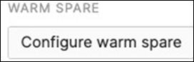
39. Spare WAN Edge Connectivity: Follow these steps to create warm-spare with two MX appliances: (Please note that this might result in a brief interruption of packet forwarding on the MX Appliance):
● Navigate to Security and SD-WAN > Monitor > Appliance status and click on Configure warm spare
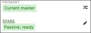
● Now click on Enabled then choose the Spare MX from the drop-down menu and then choose the Uplink IP option that suits your requirements (Please note that choosing Virtual IPs requires an additional IP address on the upstream network and a single broadcast domain between the two MXs) then click on Update

● Now click on Spare to access the Appliance status page of your Spare MX and click on the Edit button to rename the spare unit (e.g. Secondary WAN Edge)


● Then configure the following on your C9500 Core Stack:
| 9500-01#configure terminal 9500-01(config)#interface Twe1/0/2 9500-01(config-if)#switchport mode access 9500-01(config-if)#switchport access vlan 1 9500-01(config-if)#no shut 9500-01(config-if)#exit 9500-01(config)#interface Twe2/0/2 9500-01(config-if)#switchport mode access 9500-01(config-if)#switchport access vlan 1 9500-01(config-if)#no shut 9500-01(config-if)#end 9500-01#wr mem Building configuration... [OK] |
● Then connect the Spare MX downlinks to your C9500 Core Stack (e.g. Spare MX port 19 to Twe1/0/2 and port 20 to Twe2/0/2)
● Then connect the Spare MX with its uplinks (This must match the uplink configuration on your Primary WAN Edge)
● Power on the Spare MX and wait for it to come online on dashboard

● You can also verify that your C9500 Core Stack interfaces to the Spare MX are up, and that the redundant uplinks are in STP BLK mode
| 9500-01#sh ip interface brief Interface IP-Address OK? Method Status Protocol TwentyFiveGigE1/0/2 unassigned YES unset up up TwentyFiveGigE2/0/2 unassigned YES unset up up 9500-01# 9500-01#show spanning-tree MST0 Spanning tree enabled protocol mstp Root ID Priority 4096 Address b0c5.3c60.fba0 This bridge is the root Hello Time 2 sec Max Age 20 sec Forward Delay 15 sec Bridge ID Priority 4096 (priority 4096 sys-id-ext 0) Address b0c5.3c60.fba0 Hello Time 2 sec Max Age 20 sec Forward Delay 15 sec
Interface Role Sts Cost Prio.Nbr Type Twe1/0/1 Desg FWD 2000 128.193 P2p Twe1/0/2 Desg FWD 2000 128.194 P2p Twe2/0/1 Back BLK 2000 128.385 P2p Twe2/0/2 Back BLK 2000 128.386 P2p
9500-01# |
40. Access Policy configuration: When you're logged in dashboard, Navigate to Switching > Configure > Access policies to configure Access Policies as required for your Campus LAN. Please see the following example for two Access Policies; 802.1x and MAB.
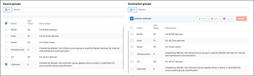
41. Adaptive Policy Configuration: Configure Adaptive Policy for your Campus LAN. When you're logged in dashboard, Navigate to Organization > Configure > Adaptive Policy then click on the Groups tab on the top.
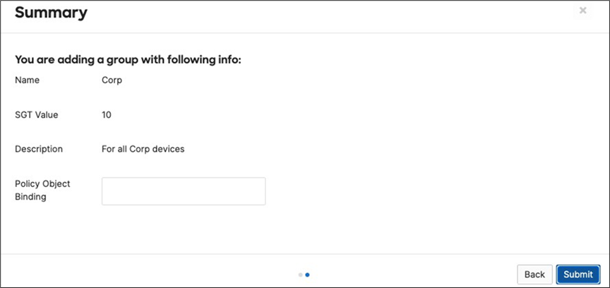
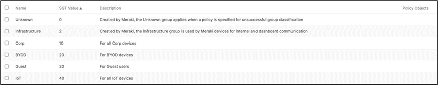
There should be two groups (Unknown, Infrastructure) that are already available. Click on Add group to add each group required for your Campus LAN. You need to fill in the Name, the SGT value, and a description then click on Review changes then click on Submit. Please see the following examples:
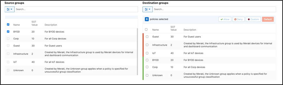
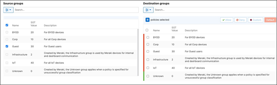
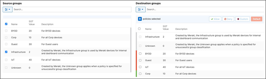
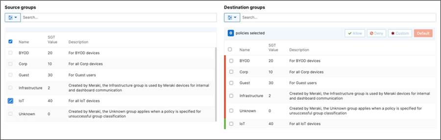
42. Adaptive Policy Configuration: Configure Adaptive Policy for your Campus LAN. When you're logged in dashboard, Navigate to Organization > Configure > Adaptive Policy then click on the Policies tab on the top. The source groups are on the left side, and the destination groups are on the right side. Select a source group from the left side then select all destination groups on the right side that should be allowed then click on Allow and click on Save at the bottom of the page. Next, select a source group from the left side then select all destination groups on the right side that should be denied (i.e. Blocked) then click on Deny and click on Save at the bottom of the page. After creating the policy for that specific source group, the allowed destination groups will be displayed with a green tab and the denied destination groups will be displayed with a red tab. Repeat this step for all policies required for all Groups (Allow and Deny).

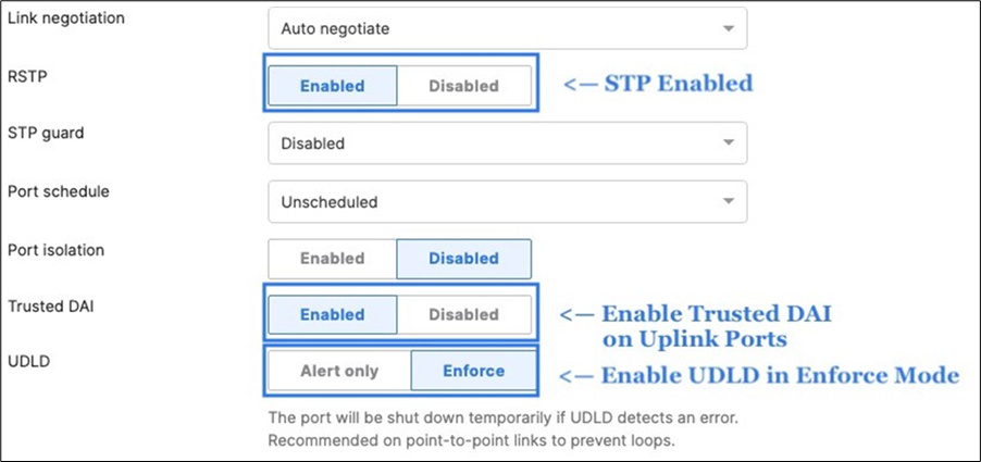
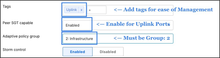
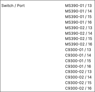
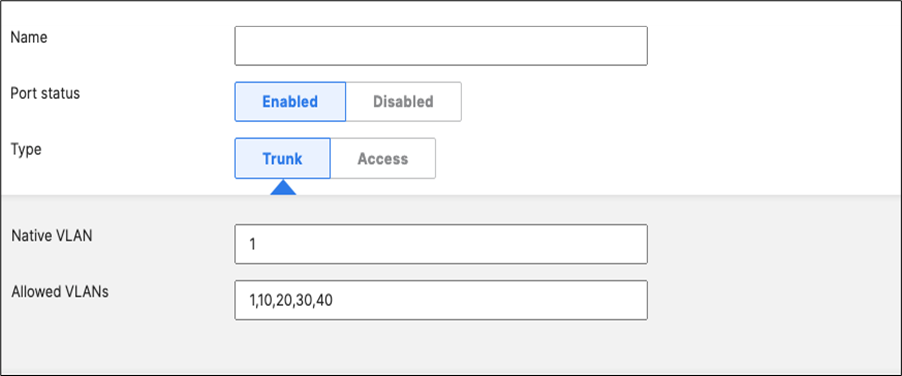
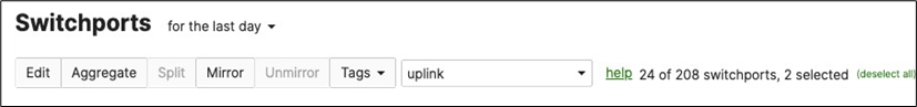
43. Access Switch Ports Configuration: Configure Uplink Ports on your Access Switches. When you're logged in dashboard, Navigate to Switching > Monitor > Switch Ports, then select your uplink ports and configure them as shown below. (Tip: You can filter for ports by using search terms in dashboard)
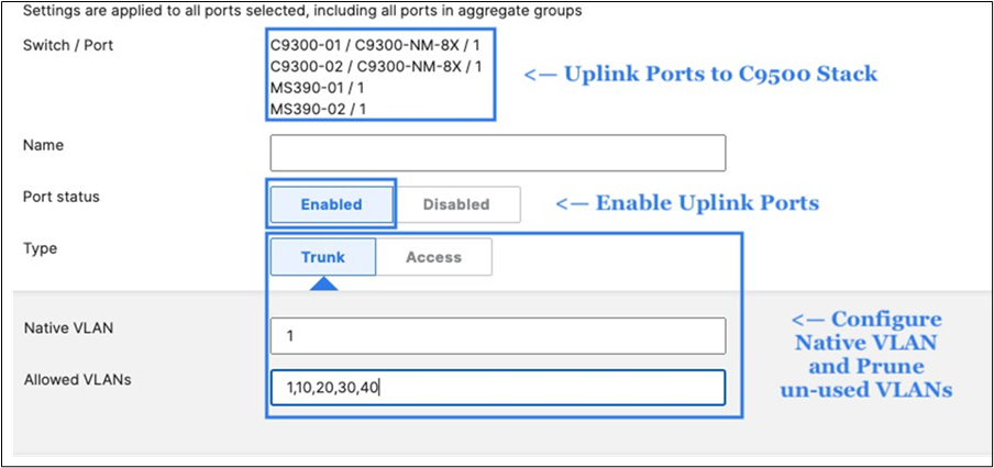
44. Optional - For ease of management, it is recommended that you rename the ports connecting to your Core switches with the actual switch name / Connecting port as shown below.

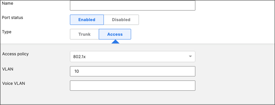
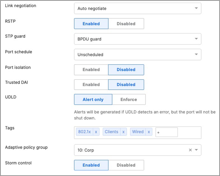
45. Access Switch Ports Configuration: Configure Wired Client Ports (802.1x) on your Access Switches. Navigate to or Refresh Switching > Monitor > Switch Ports, then select your Wired Client ports (5-8) and configure them as shown below. (Tip: You can filter for ports by using search terms in dashboard)

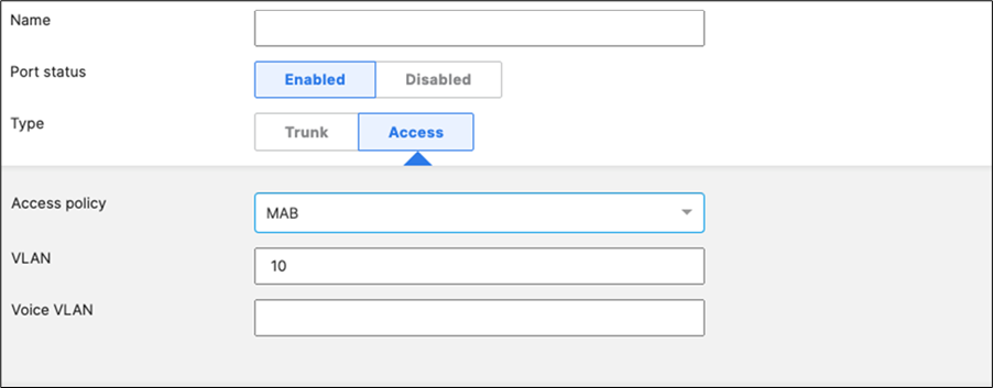
46. Access Switch Ports Configuration: Configure Wired Client Ports (MAB) on your Access Switches. Navigate to or Refresh Switching > Monitor > Switch Ports, then select your Wired Client ports (9-12) and configure them as shown below. (Tip: You can filter for ports by using search terms in dashboard)


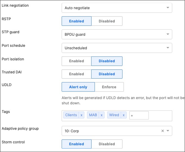
47. Access Switch Ports Configuration: Configure MR Ports on your Access Switches. Navigate to or Refresh Switching > Monitor > Switch Ports, then select your ports connecting to MR Access Points (13-16) and configure them as shown below. (Tip: You can filter for ports by using search terms in dashboard)

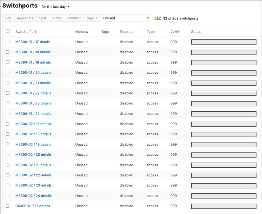
48. Optional - Access Switch Ports Configuration: Configure unused ports on your Access Switches such that they are disabled and mapped to an unrouted VLAN (e.g. VLAN 999). Navigate to Switching > Configure > Switch Ports and filter for any unused ports (e.g. 17-24) and configure them as shown below.
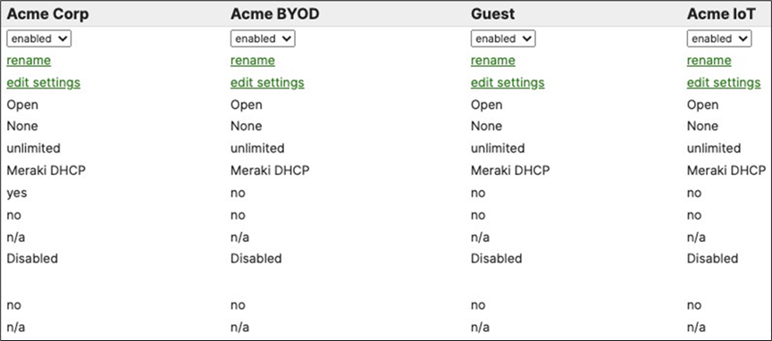
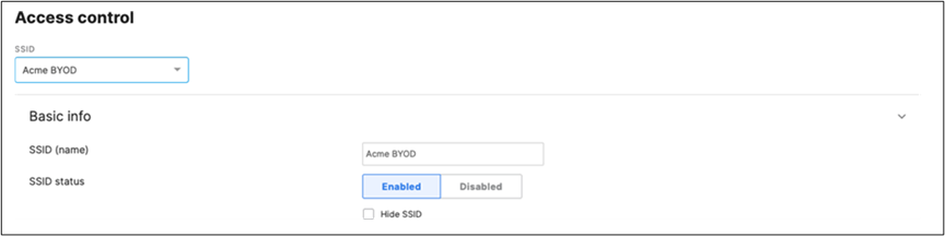
49. Rename Wireless SSIDs: To configure your SSIDs per the above table, first navigate to Wireless > Configure SSIDs then rename the SSIDs per your requirements (Refer to the above table for guidance).
● SSID#1 (First column, aka vap:0, enabled by default): Click on rename and change it to Acme Corp
● SSID#2 (Second column, aka vap:1): Click on rename and change it to Acme BYOD, then click on the top drop-down menu to enable it
● SSID#3 (Third column, aka vap:2): Click on rename and change it to Guest, then click on the top drop-down menu to enable it
● SSID#4 (Fourth column, aka vap:3): Click on rename and change it to Acme IoT, then click on the top drop- down menu to enable it
● Click Save at the bottom of the page
50. Configure Access Control for Acme Corp: Navigate to Wireless > Configure > Access control then from the top drop-down menu choose Acme Corp.
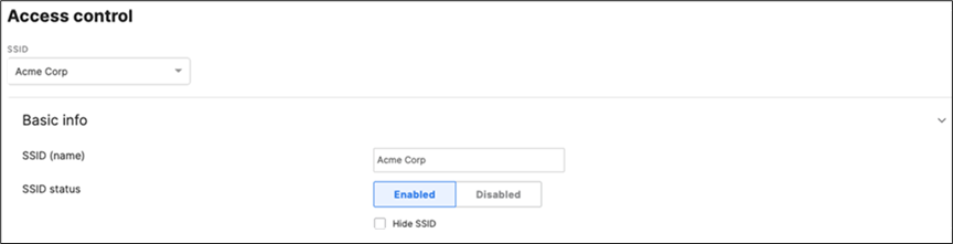

● Click Save at the bottom of the page
● Please Note: Adaptive Policy Group feature is not currently available in the New Version of the Access. You will need to click on View old version
View old version
which is available at the top right corner of the page to be able to access this and configure the Adaptive Policy Group (10: Corp). Then, please click Save at the bottom of the page
51. Configure Access Control for Acme BYOD: Navigate to Wireless > Configure > Access control then from the top drop-down menu choose Acme BYOD.

● Click on
which is available on the top right corner of the page, then choose the Adaptive Policy Group 20: BYOD and then click on Save at the bottom of the page.
52. Configure Access Control for Guest: Navigate to Wireless > Configure > Access control then from the top drop-down menu choose Guest.
● Click on
View old Version
at the top right corner of the page then choose the Adaptive Policy Group 30: Guest then click on Save at the bottom of the page
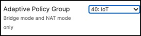
53. Configure Access Control for Acme IoT: Navigate to Wireless > Configure > Access control then from the top drop-down menu choose Acme IoT.
● Click on
View old version
at the top right corner of the page then choose the Adaptive Policy Group 40: IoT then click on Save at the
● bottom of the page
54. Enabling Stacking on your MS390 and C9300 Switches in Meraki Dashboard; please follow these steps:
A. Connect a single uplink to each switch (e.g. Port 1 on MS390-01 to Port TwentyFiveGigE1/0/23 on C9500)
B. Make sure all stacking cables are unplugged from all switches
C. Power up all switches
D. Verify that your C9500 Stack downlinks are up and not shutdown
| 9500-01#ship interface brief Interface IP-Address OK? Method Status Protocol TwentyFiveGigE1/0/23 unassigned YES unset up up TwentyFiveGigE1/0/24 unassigned YES unset up up TwentyFiveGigE2/0/23 unassigned YES unset up up TwentyFiveGigE2/0/24 unassigned YES unset up up 9500-01# |
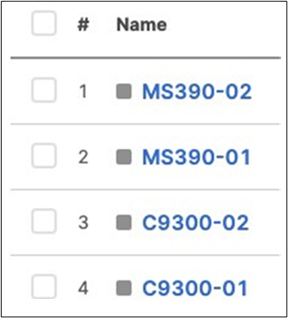
E. Wait for them to come online on dashboard. Navigate to Switching > Monitor > Switches and check the status of your Access Switches
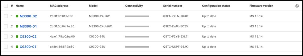
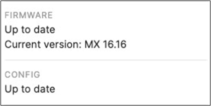
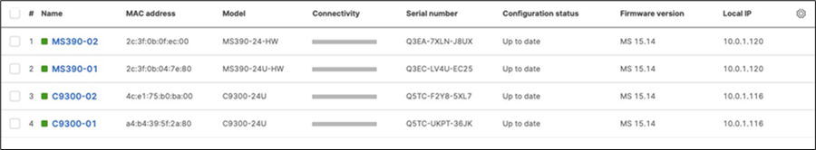
F. After they come online and download their configuration and firmware (Up to date) you can proceed to the next step. You can see their Configuration status and Firmware version from Switching > Monitor > Switches
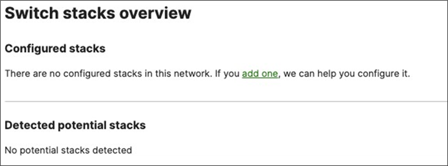
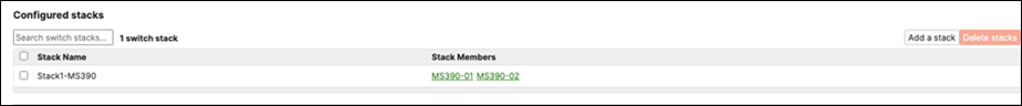
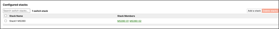
G. Enable stacking in dashboard by Navigating to Switching > Monitor > Switch stacks then click on add one
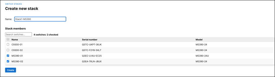
H. Then give your stack a name and select its members and click on Create
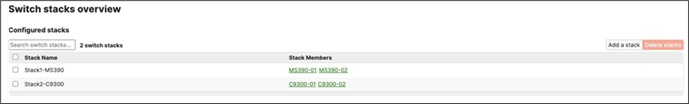
I. Now click on Add a stack to create all other stacks in your Campus LAN access layer by repeating the above steps

J. Power off all access switches
K. Disconnect all uplink cables from all switches
L. Nominate your master switch for each stack (e.g. MS390-01 for stack1 and C9300-01 for stack2)
M. On the master switches, plug the uplink again
N. Plug stacking cables on all switches in each stack to form a ring topology and make sure that the Cisco logo is upright
O. Power on your master switches first, then power other stack members
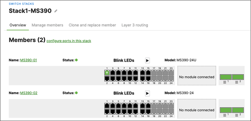
P. Wait for the stack to come online on dashboard. To check the status of your stack, Navigate to Switching > Monitor > Switch stacks and then click on each stack to verify that all members are online and that stacking cables show as connected
Q. Plug uplinks on all other non-master members and verify that the uplink is online in dashboard by navigating to Switching > Monitor > Switch stacks and then click on each stack to verify that all uplinks are showing as connected however they should be in STP discarding mode
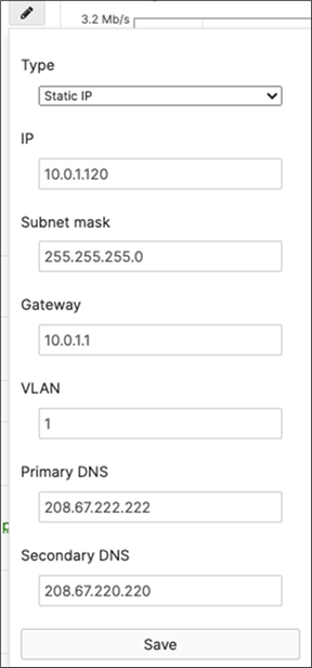
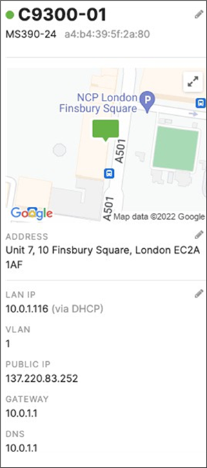
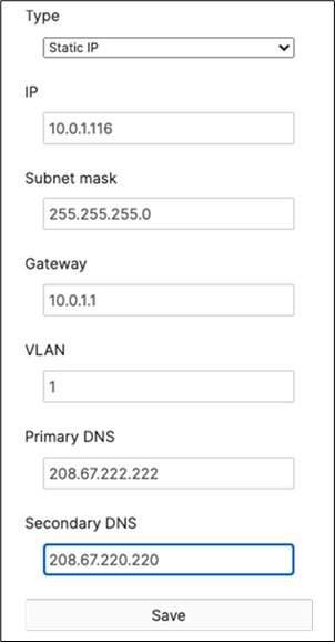
R. Configure the same Static IP for all members in each stack by navigating to Switching > Monitor > Switches then click on the master switch (e.g. MS390-01 for Stack1) and under LAN IP menu copy the IP address then click on the edit button to specify the Static IP address information (You can use the same IP address that was assigned using DHCP) then click Save. The same Static IP address information should now be copied for all members of the same stack. You can verify this by navigating to Switch > Monitor > Switches (Tip: Click on the configure button on the right-hand side of the table to add Local IP information display).
S. Finally, configure etherchannels on both your Access Switch Stacks and your Core Switch Stacks so that all uplinks can be operational (STP forwarding mode) at the same time. Follow these steps:
◦ First, disconnect the downlinks to non-master switches from your C9500 Core Stack (e.g. Port TwentyFiveGigE2/0/23 and TwentyFiveGigE2/0/24)
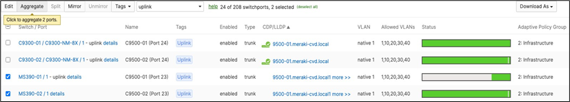
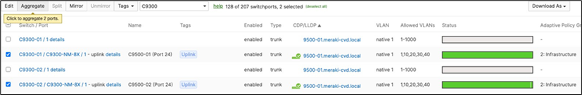
◦ Navigate to Switching > Monitor > Switch ports and search for uplink then select all uplinks in the same stack (in case you have tagged your ports otherwise search for them manually and select them all) then click on Aggregate. Please note that all port members of the same Ether Channel must have the same configuration otherwise Dashboard will not allow you to click the aggregate button.
![]()

◦ Please repeat above steps for all stacks in your network
◦ Please note that the above step will cause all members within the stack to go offline in Dashboard
● On your C9500 Core Stack, please configure etherchannel Settings for your downlinks such that each Stack downlinks should be in a separate Port-channel and that the mode is active:
| 9500-01#configure terminal Enter configuration commands, one per line. End with CNTL/Z. 9500-01(config)#interface TwentyFiveGigE1/0/23 9500-01(config-if)#channel-group 1 mode active Creating a port-channel interface Port-channel 1
9500-01(config-if)# 9500-01(config-if)#interface TwentyFiveGigE2/0/23 9500-01(config-if)#channel-group 1 mode active 9500-01(config-if)#interface TwentyFiveGigE1/0/24 9500-01(config-if)#channel-group 2 mode active Creating a port-channel interface Port-channel 2
9500-01(config-if)#interface TwentyFiveGigE2/0/24 9500-01(config-if)#channel-group 2 mode active 9500-01(config-if)#end 9500-01# 9500-01#show etherchannel 1 port-channel Port-channels in the group: ------------------------ Port-channel: Po1 (Primary Aggregator) --------------- Age of the Port-channel = 0d:01h:42m:43s Logical slot/port = 9/1 Number of ports = 2 HotStandBy port = null Port state = Port-channel Ag-Inuse Protocol = LACP Port security = Disabled Fast-switchover = disabled Fast-switchover Dampening = disabled Ports in the Port-channel:
Index Load Port EC state No of bits ------+------+------+-------------+----------- 0 00 Twe1/0/23 Active 0 0 00 Twe2/0/23 Active 0
Time since last port bundled: 0d:01h:40m:21s Twe2/0/23
9500-01# 9500-01#show etherchannel 2 port-channel Port-channels in the group: ------------------
Port-channel: Po2 (Primary Aggregator)
-----------
Age of the Port-channel = 0d:01h:43m:56s Logical slot/port = 9/2 Number of ports = 2 HotStandBy port = null Port state = Port-channel Ag-Inuse Protocol = LACP Port security = Disabled Fast-switchover = disabled Fast-switchover Dampening = disabled Ports in the Port-channel: Index Load Port EC state No of bits -------+------+------+-------------+----------- 0 00 Twe1/0/24 Active 0 0 00 Twe2/0/24 Active 0
Time since last port bundled: 0d:01h:42m:04s Twe2/0/24 9500-01#9500-01#wr mem Building configuration... [OK] 9500-01# |
● Plug all uplinks to non-master switches
● Now all your switches should come back online on Dashboard
● And now all your uplinks from each stack should be in STP Forwarding mode, which you can verify on Dashboard by navigating to Switching > Monitor > Switch stacks and checking the uplink port status. Also, you can check that on your C9500 Core Stack:
| 9500-01#show spanning-tree interface port-channel 1
Mst Instance Role Sts Cost Prio.Nbr Type ---------------------------------------------------- MST0 Desg FWD 10000 128.2089 P2p 9500-01#show spanning-tree interface port-channel 2
Mst Instance Role Sts Cost Prio.Nbr Type ---------------------------------------------------- MST0 Desg FWD 10000 128.2089 P2p 9500-01#show spanning-tree MST0 Spanning tree enabled protocol mstp Root ID Priority 4096 Address b0c5.3c60.fba0 This bridge is the root Hello Time 2 sec Max Age 20 sec Forward Delay 15 sec
Bridge ID Priority 4096 (priority 4096 sys-id-ext 0) Address b0c5.3c60.fba0 Hello Time 2 sec Max Age 20 sec Forward Delay 15 sec
Interface Role Sts Cost Prio.Nbr Type --------------------------------------------------- Twe1/0/1 Desg FWD 2000 128.193 P2p Twe1/0/2 Desg FWD 2000 128.194 P2p Twe2/0/1 Back BLK 2000 128.385 P2p Twe2/0/2 Back BLK 2000 128.386 P2p Po1 Desg FWD 10000 128.2089 P2p Po2 Desg FWD 1000 128.2090 P2p 9500-01# |
55. Configure Multiple Spanning Tree Protocol (802.1s) in Dashboard for MS390 and C9300 switches: Navigate to Switching > Configure > Switch settings and select your stack and choose the appropriate STP priority per stack (61440 for all Access Switch Stacks) then click Save at the bottom of the page.
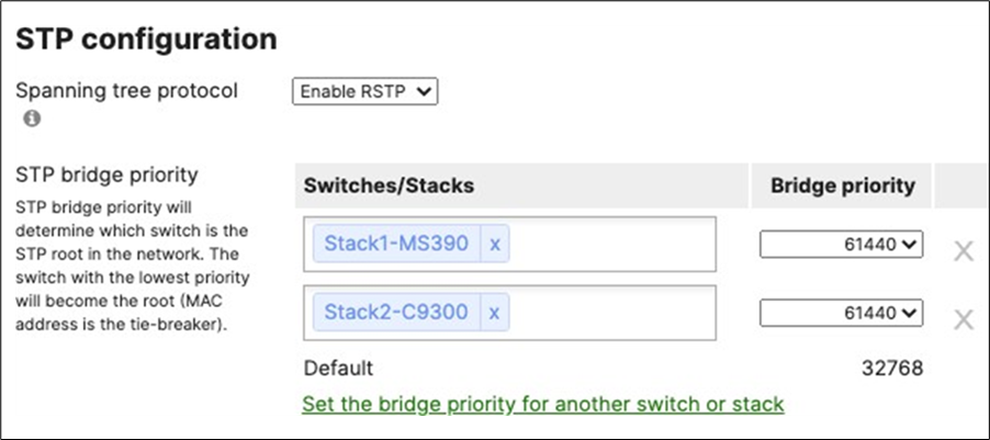
● Verify that the Access Stacks are seeing the C9500 Core Stack as the root by navigating to Switching > Monitor > Switches then click on any switch and under the RSTP root menu check the root bridge information
56. Configure Dynamic ARP Inspection (DAI) on your C9500 Core Switches: All Downlinks to Access Switches and Uplinks to MX Edge must be configured as Trusted and all other interfaces as Untrusted. (Please note that the order of commands is important to avoid loss of connectivity)
| Capability Codes: R - Router, T - Trans Bridge, B - Source Route Bridge S - Switch, H - Host, I - IGMP, r - Repeater, P - Phone, D - Remote, C - CVTA, M - Two-port Mac Relay
Device ID Local Intrfce Holdtme Capability Platform Port ID a4b4395f2a80 Twe 1/0/24 124 S C9300-24U Port C9300-NM-8X/1 2c3f0b0fec00 Twe 2/0/23 174 S MS390-24 Port 1 2c3f0b047e80 Twe 1/0/23 159 S MS390-24U Port 1 4ce175b0ba00 Twe 2/0/24 177 S C9300-24U Port C9300-NM-8X/1
Total cdp entries displayed : 4 9500-01#configure terminal 9500-01(config)#interface TwentyFiveGigE1/0/1 9500-01(config-if)#ip arp inspection trust 9500-01(config-if)#ip dhcp snooping trust 9500-01(config-if)#exit 9500-01(config)#interface TwentyFiveGigE1/0/2 9500-01(config-if)#ip arp inspection trust 9500-01(config-if)#ip dhcp snooping trust 9500-01(config-if)#exit 9500-01(config)#interface TwentyFiveGigE2/0/1 9500-01(config-if)#ip arp inspection trust 9500-01(config-if)#ip dhcp snooping trust 9500-01(config-if)#exit 9500-01(config)#interface TwentyFiveGigE2/0/2 9500-01(config-if)#ip arp inspection trust 9500-01(config-if)#ip dhcp snooping trust 9500-01(config-if)#exit 9500-01(config)#interface Po1 9500-01(config-if)#ip arp inspection trust 9500-01(config-if)#ip dhcp snooping trust 9500-01(config-if)#exit 9500-01(config)#interface Po2 9500-01(config-if)#ip arp inspection trust 9500-01(config-if)#ip dhcp snooping trust 9500-01(config-if)#exit 9500-01(config)#ip arp inspection vlan 1,10,20,30,40 9500-01(config)#ip dhcp snooping vlan 1,10,20,30,40 9500-01(config)#end 9500-01#show ip dhcp snooping Switch DHCP snooping is enabled Switch DHCP gleaning is disabled DHCP snooping is configured on following VLANs: 1,10,20,30,40 DHCP snooping is operational on following VLANs: 1,10,20,30,40 DHCP snooping is configured on the following L3 Interfaces:
Insertion of option 82 is enabled circuit-id default format: vlan-mod-port remote-id: b0c5.3c60.fba0 (MAC) Option 82 on untrusted port is not allowed Verification of hwaddr field is enabled Verification of giaddr field is enabled DHCP snooping trust/rate is configured on the following Interfaces:
Interface Trusted Allow option Rate limit (pps) ------------------------------------------------------------------------ TwentyFiveGigE1/0/1 yes yes unlimited Custom circuit-ids: TwentyFiveGigE1/0/2 yes yes unlimited Custom circuit-ids: TwentyFiveGigE1/0/23 yes yes unlimited Custom circuit-ids: TwentyFiveGigE1/0/24 yes yes unlimited Custom circuit-ids: TwentyFiveGigE2/0/1 yes yes unlimited Custom circuit-ids: TwentyFiveGigE2/0/2 yes yes unlimited Custom circuit-ids: TwentyFiveGigE2/0/23 yes yes unlimited Custom circuit-ids: TwentyFiveGigE2/0/24 yes yes unlimited Custom circuit-ids: Port-channel1 yes yes unlimited Custom circuit-ids: Port-channel2 yes yes unlimited Custom circuit-ids: 9500-01# 9500-01#show ip arp inspection
Source Mac Validation : Disabled Destination Mac Validation : Disabled IP Address Validation : Disabled
Vlan Configuration Operation ACL Match Static ACL ----------------------------------------------------- 1 Enabled Active 10 Enabled Active 20 Enabled Active 30 Enabled Active 40 Enabled Active 9500-01#wr mem Building configuration... [OK] 9500-01# |
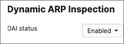
57. Configure Dynamic Arp Inspection (DAI) on your Access Switch Stacks: Navigate to Switching > Monitor > DHCP Servers and ARP and scroll down to Dynamic ARP Inspection and enable it. Then click Save at the bottom of the page.
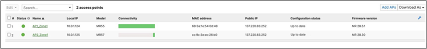
58. Setting up your Access Points: Connect your APs to the respective ports on the Access Switches (e.g. Ports 13-16) and wait for them to come online on dashboard and download their firmware and configuration files. To check the status of your APs navigate to Wireless > Monitor > Access points and check the status, configuration and firmware of your APs.
59. Re-addressing your Network Devices: In this step, you will adjust your IP addressing configuration to align with your network design. This step could have been done earlier in the process however it will be easier to adjust after all your network devices have come online since the MX (The DHCP server for Management VLAN 1) has kept a record of the actual MAC addresses of all DHCP clients. Follow these steps to re-assign the desired IP addresses: (Please note that this will cause disruption to your network connectivity)
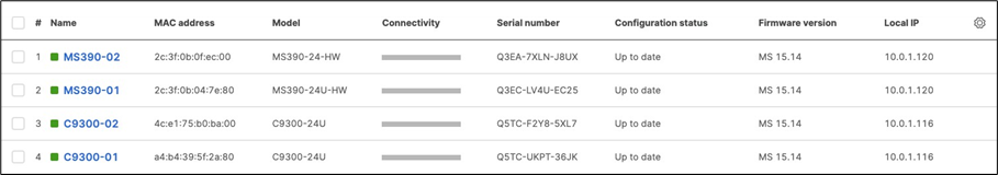
A. Navigate to Organization > Monitor > Overview then click on Devices tab to check the current IP addressing for your network devices
B. Navigate to Security and SD-WAN > Monitor > Appliance status then click on the Tools tab and click on Run next to ARP Table
C. Take a note of the MAC addresses of your network devices
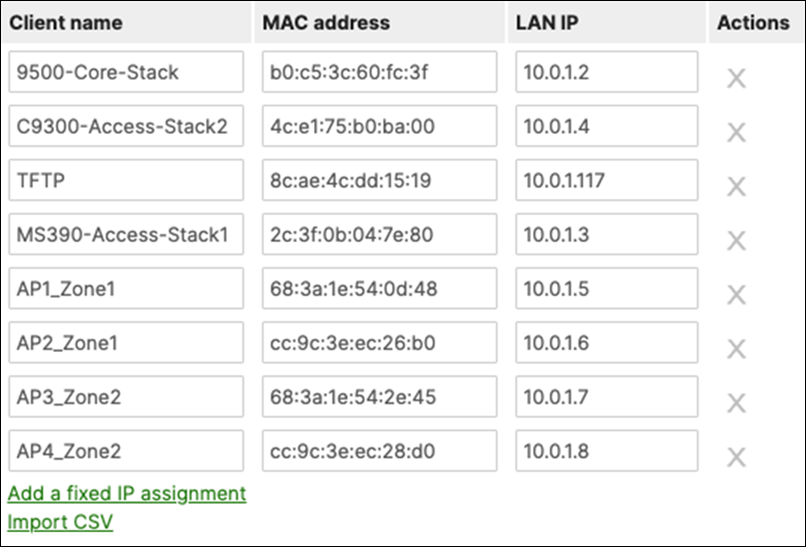
D. Navigate to Security and SD-WAN > Configure > DHCP then under Fixed IP assignments click on Add a fixed IP assignment and add entries for your network devices using the MAC addresses you have from Step #3 above then click on Save at the bottom of the page
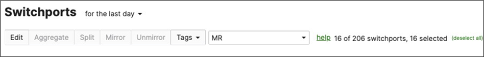
E. Navigate to Switching > Configure > Switch ports then filter for MR (in case you have previously tagged your ports or select ports manually if you haven't) then select those ports and click on Edit, then set Port status to Disabled then click on Save.
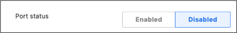
F. After a few minutes (For configuration to be up to date) Navigate to Switching > Configure > Switch ports then filter for MR (in case you have previously tagged your ports or select ports manually if you haven't) then select those ports and click on Edit, then set Port status to Enabled then click on Save.


G. Navigate to Switching > Monitor > Switches then click on each master switch to change its IP address to the one desired using Static IP configuration (remember that all members of the same stack need to have the same static IP address)
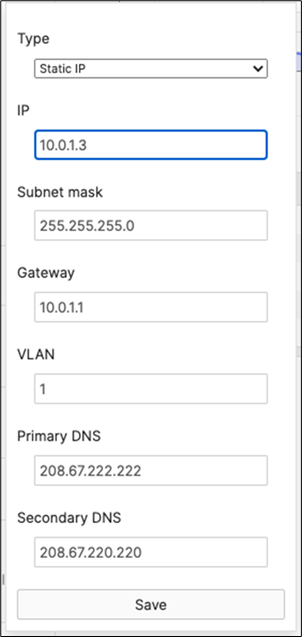
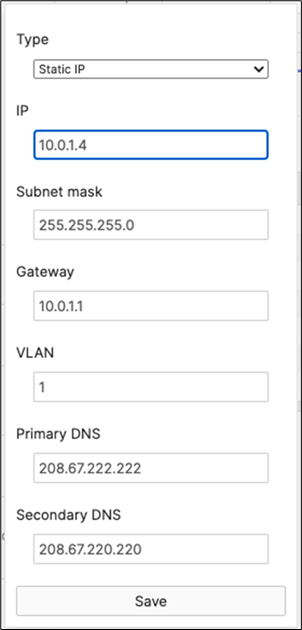
H. On your C9500 Core Stack, bounce your VLAN 1 interface. Then verify that the interface VLAN 1 came up with the correct IP address (e.g. 10.0.0.2 per this design)
| 9500-01#configure terminal Enter configuration commands, one per line. End with CNTL/Z. 9500-01(config)#interface vlan 1 9500-01(config-if)#shutdown 9500-01(config-if)#no shutdown 9500-01(config-if)#end 9500-01#sh ip interface brief vlan 1 Interface IP-Address OK? Method Status Protocol Vlan1 10.0.1.2 YES DHCP up up 9500-01# |
I. Navigate to Organization > Monitor > Overview then click on Devices tab to check the current IP addressing for your network devices
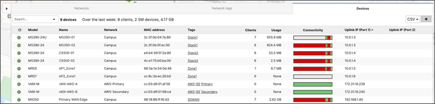
60. Configure QoS in your Campus LAN: Quality of Service configuration needs to be consistent across the whole Campus LAN. Please refer to the above table as an example. To configure QoS, please follow these steps: (For the purpose of this CVD, Default traffic shaping rules will be used to mark traffic with DSCP values without setting any traffic limits. Please adjust traffic shaping rules based on your own requirements)
A. Navigate to Wireless > Configure > Firewall and Traffic Shaping and choose the Acme Corp SSID from the above drop-down menu. Under Traffic Shaping rules, choose the per-client and per-SSID limits desired and select Shape traffic on this SSID then select Enable default traffic shaping rules. Click Save at the bottom of the page when you are done. Click Save at the bottom of the page when you are done.
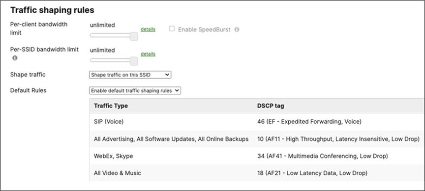
B. Navigate to Wireless > Configure > Firewall and Traffic Shaping and choose the Acme BYOD SSID from the above drop-down menu. Under Traffic Shaping rules, choose the per-client and per-SSID limits desired and select Shape traffic on this SSID then select Enable default traffic shaping rules.
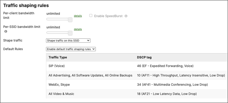
C. Navigate to Wireless > Configure > Firewall and Traffic Shaping and choose the Guest SSID from the above drop-down menu. Under Traffic Shaping rules, choose the per-client and per-SSID limits desired and select Shape traffic on this SSID then select Enable default traffic shaping rules. Click Save at the bottom of the page when you are done.
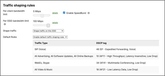
D. Navigate to Wireless > Configure > Firewall and Traffic Shaping and choose the IoT SSID from the above drop-down menu. Under Traffic Shaping rules, choose the per-client and per-SSID limits desired and select Shape traffic on this SSID then select Enable default traffic shaping rules. Click Save at the bottom of the page when you are done.
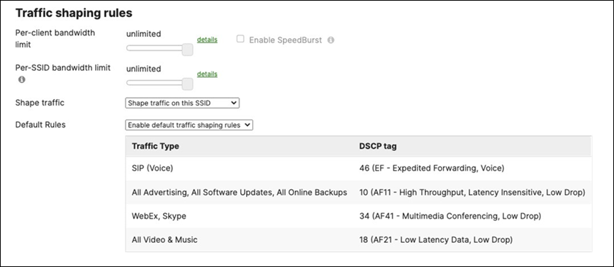
E. Navigate to Switching > Configure > Switch settings and under the Quality of Service menu configure the VLAN to DSCP mappings. Please click on Edit DSCP to CoS map to change settings per your requirements. (For more information on MS QoS settings and operation, please refer to the following article) Click Save at the bottom of the page when you are done. (Please note that the ports used in the below example are based on Cisco Webex traffic flow)
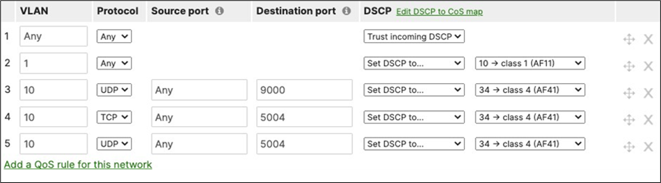
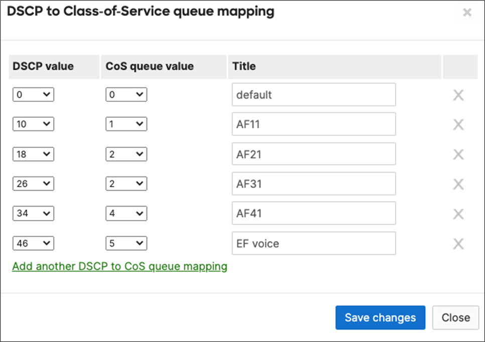
F. Please ensure that your C9500 Core Stack is configured to trust incoming QoS. Here's a reference of the configuration needed to be applied:
| 9500-01#configure terminal Enter configuration commands, one per line. End with CNTL/Z. 9500-01(config)#interface TwentyFiveGigE1/0/1 9500-01(config-if)#auto qos trust dscp 9500-01(config-if)#interface TwentyFiveGigE1/0/2 9500-01(config-if)#auto qos trust dscp 9500-01(config-if)#interface TwentyFiveGigE2/0/1 9500-01(config-if)#auto qos trust dscp 9500-01(config-if)#interface TwentyFiveGigE2/0/2 9500-01(config-if)#auto qos trust dscp 9500-01(config-if)#interface TwentyFiveGigE1/0/23 9500-01(config-if)#auto qos trust dscp Warning: add service policy will cause inconsistency with port TwentyFiveGigE2/0/23 in ether channel 1. 9500-01(config-if)#interface TwentyFiveGigE1/0/24 9500-01(config-if)#auto qos trust dscp Warning: add service policy will cause inconsistency with port TwentyFiveGigE2/0/24 in ether channel 2. 9500-01(config-if)#interface TwentyFiveGigE1/0/24 9500-01(config-if)#auto qos trust dscp 9500-01(config-if)#end 9500-01#show auto qos
TwentyFiveGigE1/0/1 auto qos trust dscp
TwentyFiveGigE1/0/2 auto qos trust dscp
TwentyFiveGigE1/0/23 auto qos trust dscp
TwentyFiveGigE1/0/24 auto qos trust dscp
TwentyFiveGigE2/0/1 auto qos trust dscp
TwentyFiveGigE2/0/2 auto qos trust dscp
TwentyFiveGigE2/0/23 auto qos trust dscp
TwentyFiveGigE2/0/24 auto qos trust dscp
9500-01#wr mem |
G. Navigate to Security and SD-WAN > Configure > SD-WAN and Traffic shaping and make sure your Uplink configuration matches your WAN speed. Then, under Uplink selection choose the settings that match your requirements (e.g. Load balancing). Under Traffic shaping rules, select Enable default traffic shaping rules then click on Add a new shaping rule to create the rules needed for your network (for more information about Traffic shaping rules on MX appliances, please refer to the following article). Please see the following example:
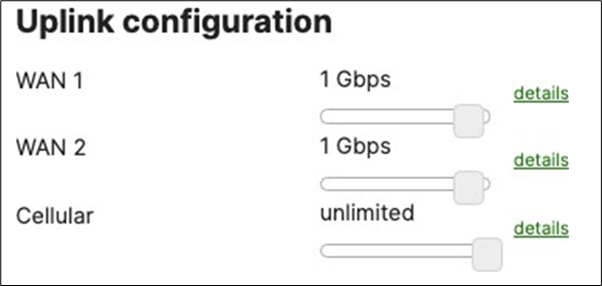
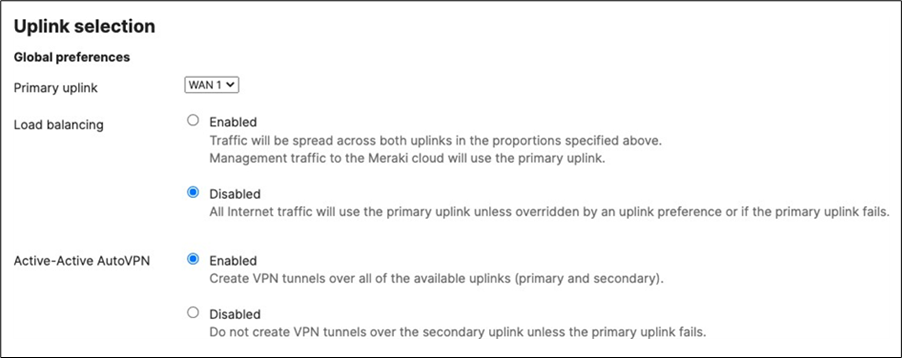

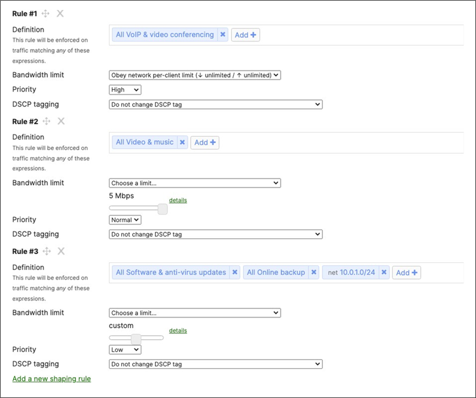
For more information about any of the above configurations, please refer to Meraki Documentation for further guidance on configuring Etherchannels, stacking, switch ports, SSId configuration and more. Here is a useful MR – Wireless section and a MS – Switching section.
Testing and Verification
Firmware
The following table indicates the firmware versions used in this Campus LAN:
| Device |
Firmware Version |
Notes |
| MX250 WAN Edge |
MX 16.16 |
GA |
| C9500 Core Stack |
IOS XE 17.3.4 |
Stable |
| MS390 Access Stack |
MS 15.14 |
Beta |
| C9300 Access Stack |
MS 15.14 |
Beta |
| MR55 |
28.6.1 |
GA |
| C9166 (MR57) |
28.30 |
Beta |
Device Connectivity
MX WAN Edge
Upstream Connectivity
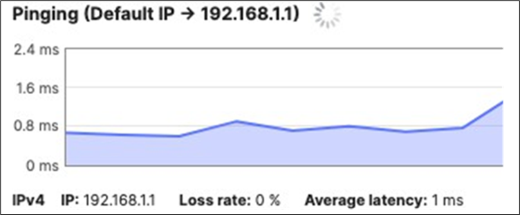
Internet/Cloud Connectivity
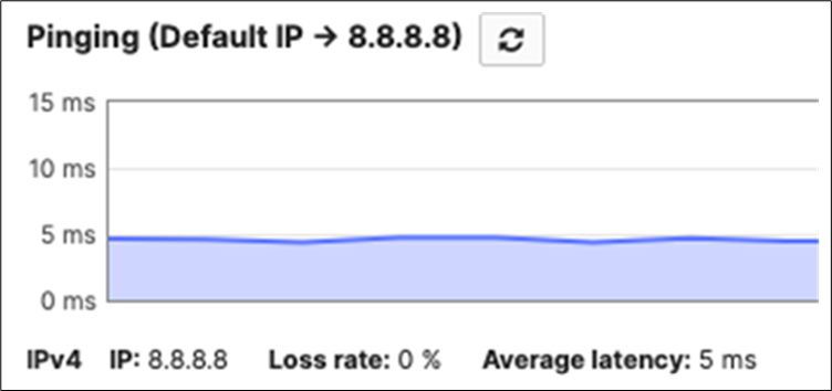
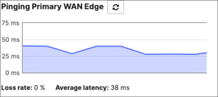
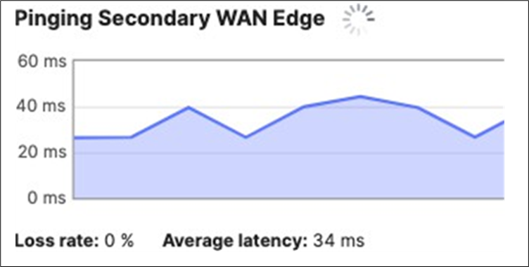
Downstream Connectivity
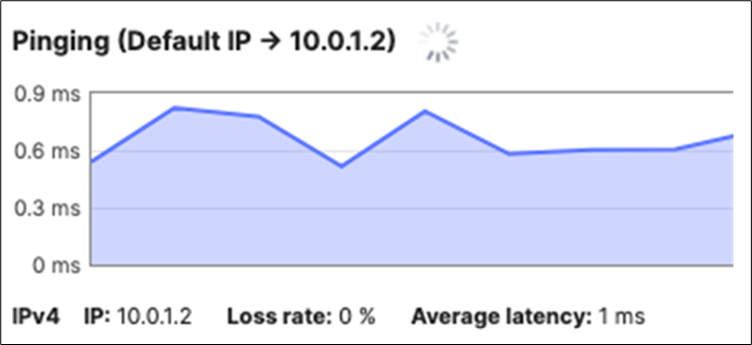
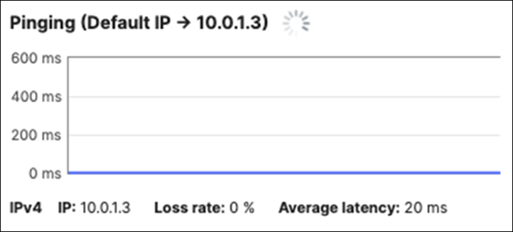
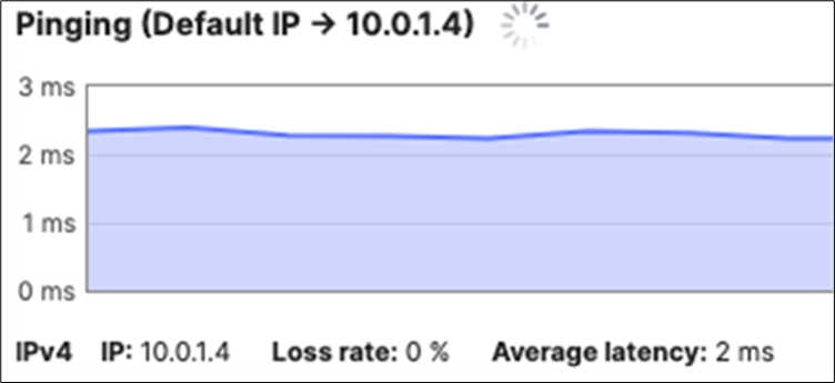

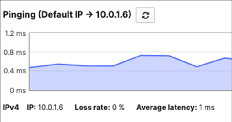
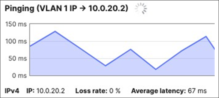
C9500 Core Stack
Upstream Connectivity
| 9500-01#ping 10.0.1.1 Type escape sequence to abort. Sending 5, 100-byte ICMP Echos to 10.0.1.1, timeout is 2 seconds: !!!!! Success rate is 100 percent (5/5), round-trip min/avg/max = 1/1/1 ms 9500-01# |
Internet Connectivity
| 9500-01#ping 8.8.8.8 Type escape sequence to abort. Sending 5, 100-byte ICMP Echos to 8.8.8.8, timeout is 2 seconds: !!!!! Success rate is 100 percent (5/5), round-trip min/avg/max = 5/5/5 ms 9500-01#ping cisco.com Type escape sequence to abort. Sending 5, 100-byte ICMP Echos to 72.163.4.185, timeout is 2 seconds: !!!!! Success rate is 100 percent (5/5), round-trip min/avg/max = 108/110/112 ms 9500-01# |
Downstream Connectivity (Please note that the MS390 and C9300-M platforms will prioritize packet forwarding over ICMP echo replies so it's expected behavior that you might get some drops)
| 9500-01#ping 10.0.1.3 Type escape sequence to abort. Sending 5, 100-byte ICMP Echos to 10.0.1.3, timeout is 2 seconds: .!!!! Success rate is 80 percent (4/5), round-trip min/avg/max = 2/2/3 ms 9500-01#ping 10.0.1.4 Type escape sequence to abort. Sending 5, 100-byte ICMP Echos to 10.0.1.4, timeout is 2 seconds: .!!!! Success rate is 80 percent (4/5), round-trip min/avg/max = 2/2/4 ms 9500-01#ping 10.0.1.5 Type escape sequence to abort. Sending 5, 100-byte ICMP Echos to 10.0.1.5, timeout is 2 seconds: !!!!! Success rate is 100 percent (5/5), round-trip min/avg/max = 1/1/1 ms 9500-01#ping 10.0.1.6 Type escape sequence to abort. Sending 5, 100-byte ICMP Echos to 10.0.1.6, timeout is 2 seconds: !!!!! Success rate is 100 percent (5/5), round-trip min/avg/max = 1/1/1 ms 9500-01# |
In case of connectivity issues, please check the following:
| Item |
Expected Configuration/ Status |
Verification |
Actual Configuration |
| C9500 Uplinks to MX Edge: TwentyFiveGigE1/0/1 TwentyFiveGigE1/0/2 TwentyFiveGigE2/0/1 TwentyFiveGigE2/0/2 |
Access , VLAN 1 DAI Trusted up/up |
sh ip int brief sh run int <interface> sh spanning-tree int <interface> |
!all uplinks! switchport mode access ip arp inspection trust ip dhcp snooping trust end ! |
| STP interface configuration: |
STP Configuration |
|
|
| TwentyFiveGigE1/0/1 TwentyFiveGigE1/0/2 TwentyFiveGigE2/0/1 TwentyFiveGigE2/0/2 TwentyFiveGigE1/0/23 TwentyFiveGigE1/0/24 TwentyFiveGigE2/0/23 TwentyFiveGigE2/0/24 |
N/A N/A N/A N/A Root Guard + UDLD aggressive Root Guard + UDLD aggressive Root Guard + UDLD aggressive Root Guard + UDLD aggressive |
sh run int <interface> |
!where applicable!
udld port aggressive
spanning-tree guard root
end
! |
| STP interface status: |
|||
| TwentyFiveGigE1/0/1 TwentyFiveGigE1/0/2 TwentyFiveGigE2/0/1 TwentyFiveGigE2/0/2 Po1 Po2 |
STP status: FWD BLK FWD BLK FWD FWD |
sh spanning-tree int <interface> |
!only PHY interfaces! spanning-tree mode mst spanning-tree extend system-id ! spanning-tree mst configuration name region1 revision 1 ! spanning-tree mst 0 priority 4096 ! |
| Default Route |
DHCP, VLAN 1 |
sh int vlan1 sh ip route |
! interface Vlan1 ip address dhcp end ! sh ip route | in /0 S* 0.0.0.0/0 [254/0] via 10.0.1.1 |
| MX WAN Edge Downlinks: Port 19 Port 20 |
Access, VLAN 1 |
Navigate to Security and SD-WAN > Configure > Addressing and VLANs |
|
| C9500 Downlinks: |
|||
| TwentyFiveGigE1/0/23 TwentyFiveGigE1/0/24 TwentyFiveGigE2/0/23 TwentyFiveGigE2/0/24 |
Trunk, Native VLAN 1, Allowed VLANs 1,10,20,30,40 DAI Trusted SGT 2 Trusted No CTS enforcement |
sh run int <interface> |
! switchport trunk allowed vlan 1,10,20,30,40 switchport mode trunk ip arp inspection trust ! cts manual policy static sgt 2 trusted no cts role-based enforcement ! End |
| C9500 Ether-Channels: |
|||
| TwentyFiveGigE1/0/23 TwentyFiveGigE1/0/24 TwentyFiveGigE2/0/23 TwentyFiveGigE2/0/24 Po1 Po2 |
Channel-Group 1 Channel-Group 2 Channel-Group 1 Channel-Group 2 up/up up/up |
sh run int <interface> sh etherchannel <#> sum sh ip int brief | in Po |
!PHY 23! channel-group 1 mode active !PHY 24! channel-group 2 mode active ! End |
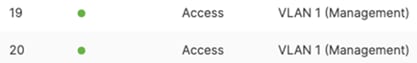
MS390 Access Stack
Upstream Connectivity
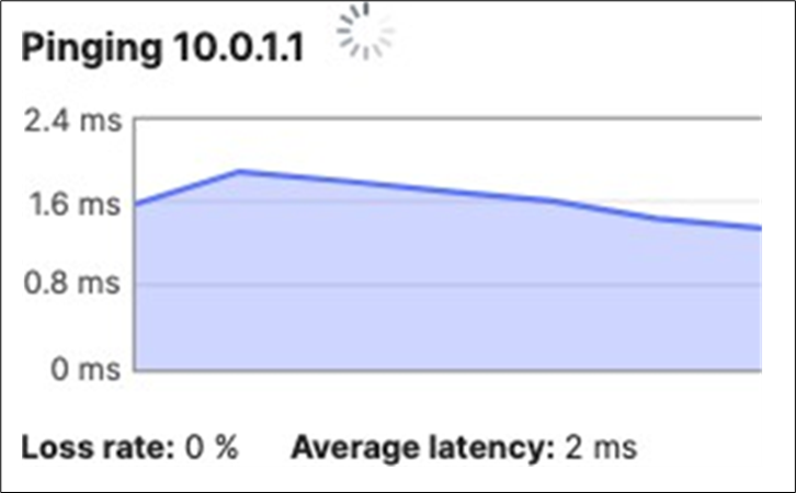
Internet/Cloud Connectivity
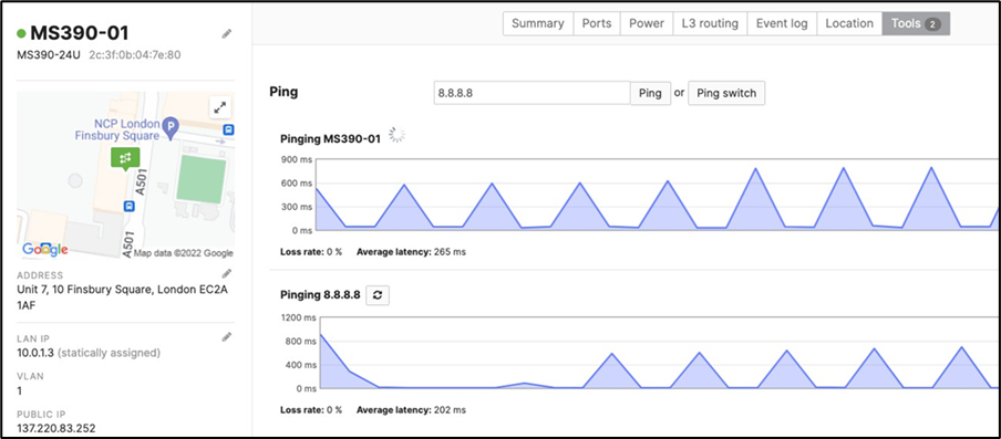
Downstream Connectivity
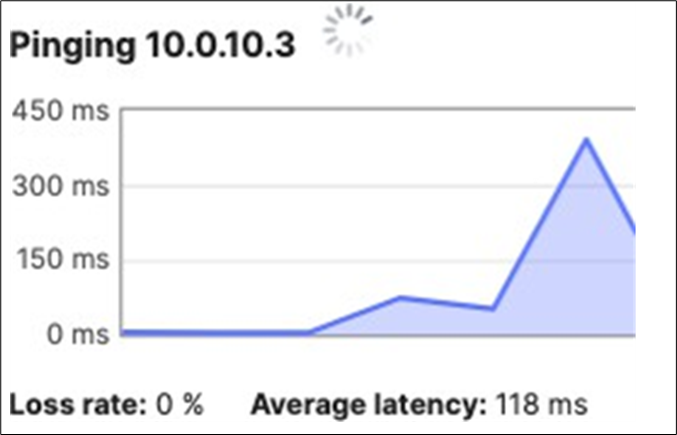
C9300 Access Stack
Upstream Connectivity
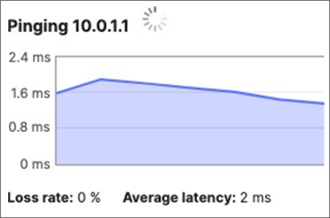
Internet/Cloud Connectivity
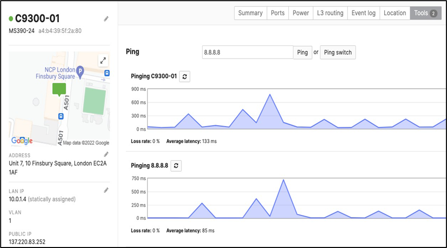
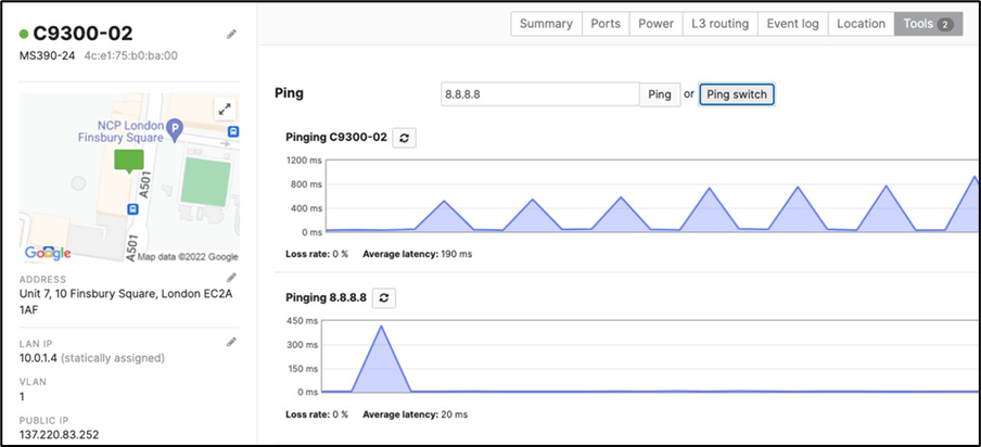
Downstream Connectivity
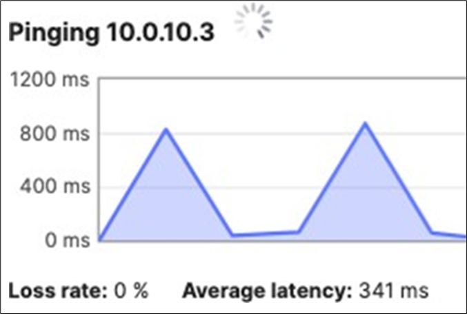
MR Access Points
Client Connectivity
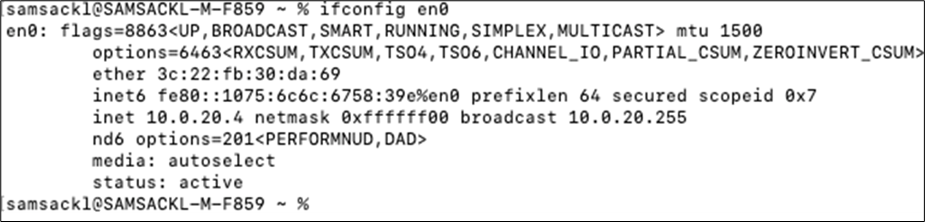
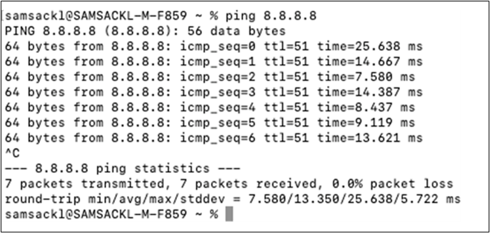
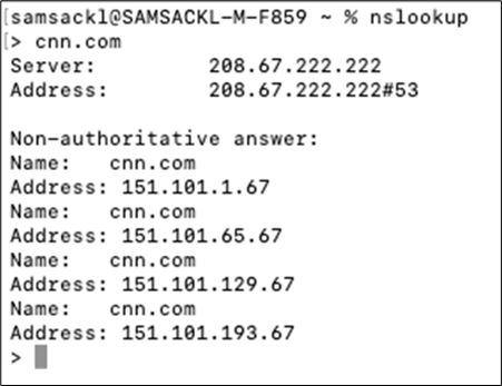
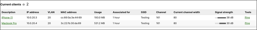
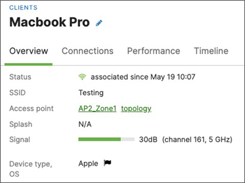
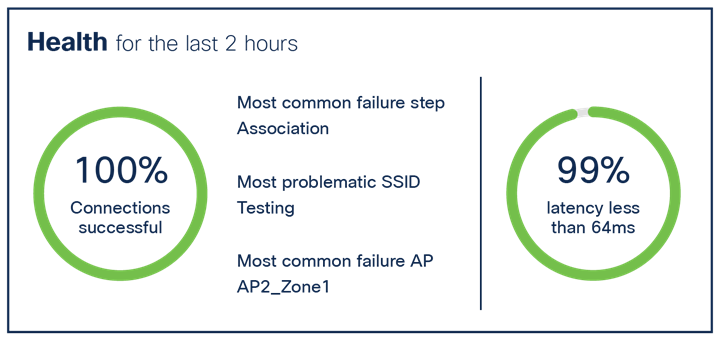
802.1x Authentication
802.1x authentication has been tested on both Corp and BYOD SSIDs. Dashboard will be checked to verify the correct IP address assignment and username. Packet captures will also be checked to verify the correct SGT assignment. In the final section, ISE logs will show the authentication status and authorization policy applied.
| Client |
SSID / Port |
Username |
VLAN |
SGT |
| MacBook Pro 3c:22:fb:30:da:69 10.0.10.3 |
Acme Corp |
Corp1 |
10 |
10 |
| iPhone 11 46:f2:0c:4b:e7:fd 10.0.20.5 |
Acme BYOD |
Byod1 |
20 |
20 |
| MacBook Pro 8C:AE:4C:DD:15:19 10.0.10.6 |
MS390-01 Port 6 |
Corp1 |
10 (Auth-fail VLAN 30) |
10 |

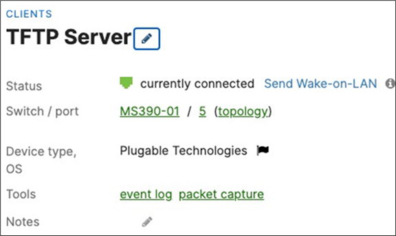
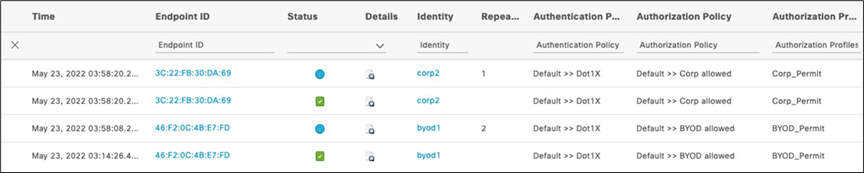
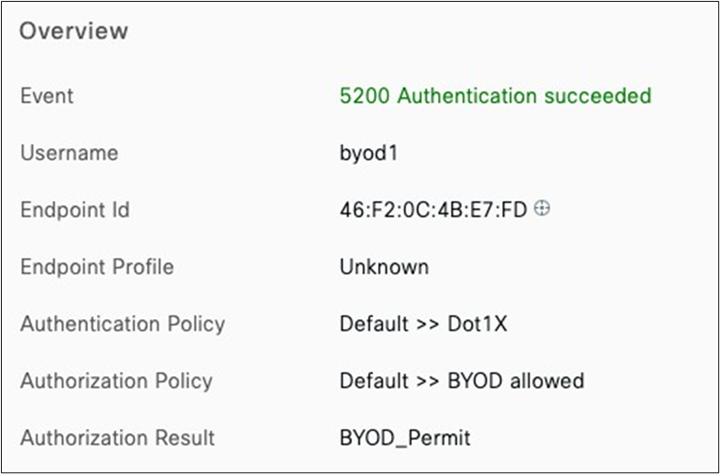

Authentication Details
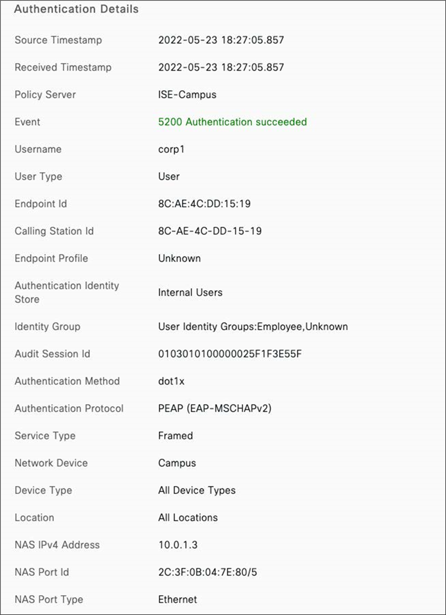
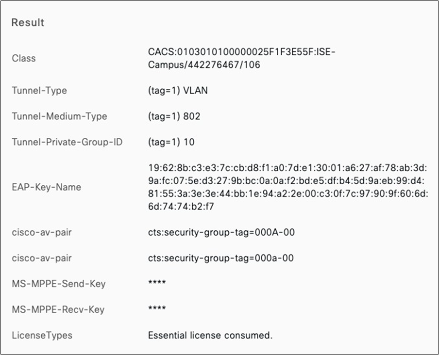
| Note: Please note that the configuration of Cisco ISE is out of scope of this CVD. Please refer to Cisco ISE administration guide for details on configuring policy sets on Cisco ISE. Also, please refer to this article for more information on the configuration of Cisco ISE with Cisco Meraki devices. |
Wireless roaming
Wireless roaming has been tested between two zones and APs homed to different switch stacks whilst being on a Webex meeting with Audio/Video and Content share. Device and Client details in the following table:
| Device Type |
Details |
Connected to |
| MR55 (AP3_Zone2) |
68:3a:1e:54:0d:48 10.0.1.5 |
C9300-2 (Stack2) |
| MR57 (AP2_Zone1) |
cc:9c:3e:ec:26:b0 10.0.1.6 |
MS390-1 (Stack1) |
| Client (iPhone 11) |
cc:66:0a:3e:44:69 10.0.20.3 |
AP3_Zone2 AP2_Zone1 (Layer 2 Roaming) |
First association
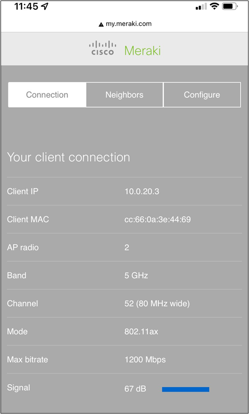
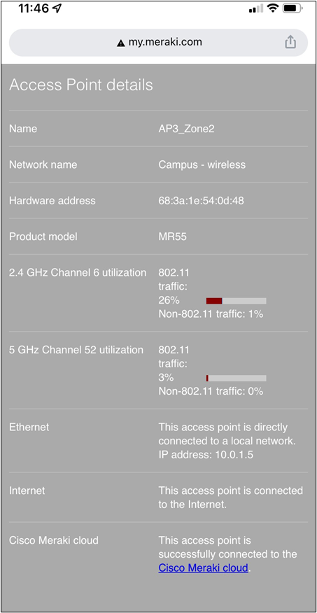
Second Association (The video overlay is the stream from a Webex meeting while the client was roaming)
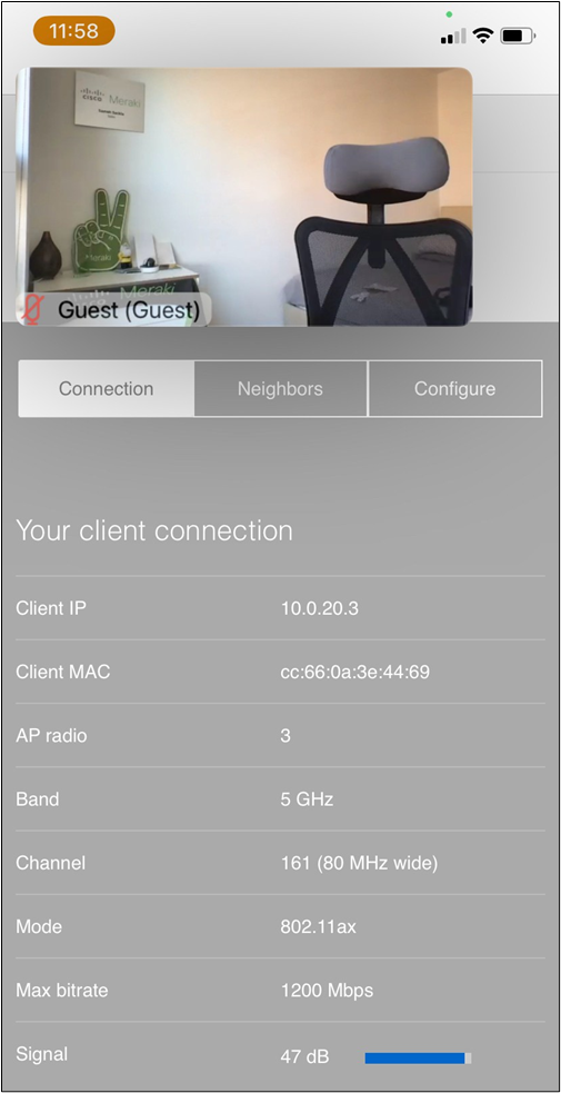
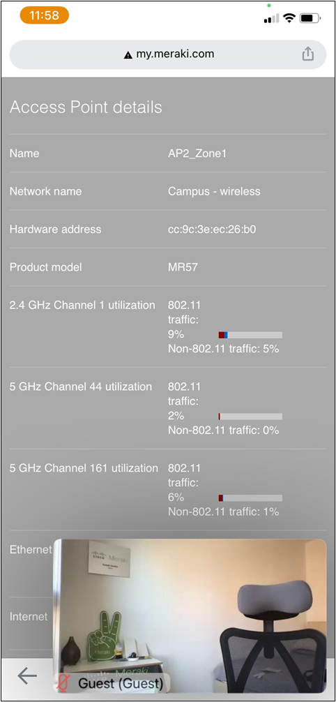
Traffic Flow (Packet #27)
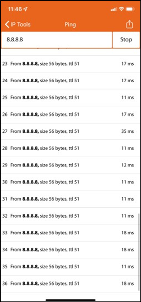
Webex meeting statistics (Snapshot taken after roaming)
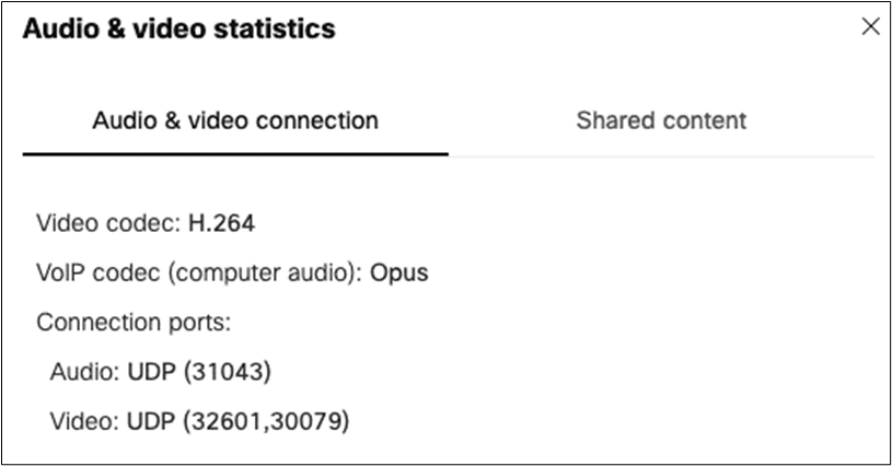
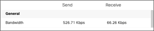
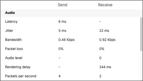
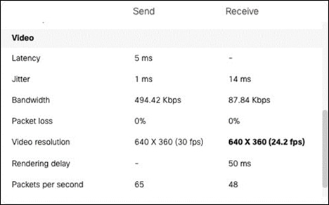
Dashboard logs
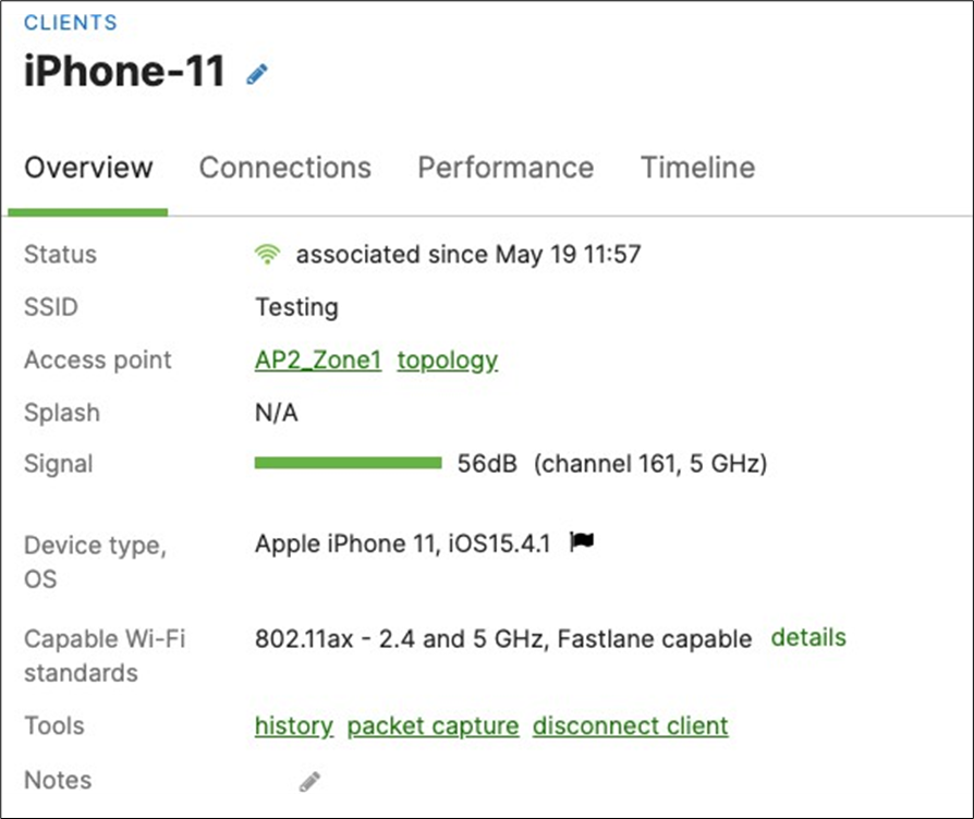
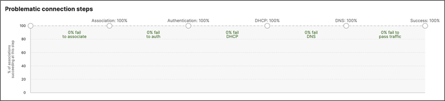
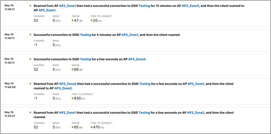
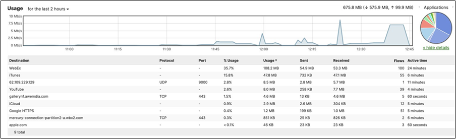
STP Convergence
STP convergence will be tested using several methods as outlined below. Please see the following table for steady-state of the Campus LAN before testing:
|
|
|
Bridge ID |
STP Status |
| C9500-01 |
Master |
4096:b0c5.3c60.fba0 |
|
| C9500-02 |
Member |
4096.40b5.c111.01e0 |
|
| MS390-01 |
Master |
61440:2c3f.0b04.7e80 |
STP ROOT b0:c5:3c:60:fb:a0 (priority 4096) |
| MS390-02 |
Member |
|
Blocking ports None |
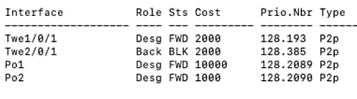

Introducing loops (Access to Core)
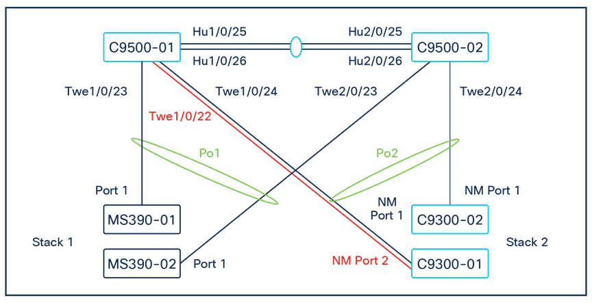
A loop was introduced by adding a link between C9300-01 /NM Port 2 and C9500 Core Stack / Port TwentyFiveGigE1/0/22 (Please note that for the purposes of this test, the interface has been unshut and configured as a Trunk port with Native VLAN 1 with STP guards on that interface).
| 9500-01#show ip interface brief | in TwentyFiveGigE1/0/22 TwentyFiveGigE1/0/22 unassigned YES unset up up ow9500-01#show run interface TwentyFiveGigE1/0/22 Building configuration...
Current configuration : 132 bytes ! interface TwentyFiveGigE1/0/22 switchport trunk allowed vlan 1,10,20,30,40 switchport mode trunk spanning-tree guard root end
9500-01# 9500-01#show spanning-tree
MST0 Spanning tree enabled protocol mstp Root ID Priority 4096 Address b0c5.3c60.fba0 This bridge is the root Hello Time 2 sec Max Age 20 sec Forward Delay 15 sec
Bridge ID Priority 4096 (priority 4096 sys-id-ext 0) Address b0c5.3c60.fba0 Hello Time 2 sec Max Age 20 sec Forward Delay 15 sec
Interface Role Sts Cost Prio.Nbr Type ------------------------------------------------- Twe1/0/1 Desg FWD 2000 128.193 P2p Twe1/0/2 Desg FWD 2000 128.194 P2p Twe1/0/22 Desg FWD 2000 128.214 P2p Twe2/0/1 Back BLK 2000 128.385 P2p Twe2/0/2 Back BLK 2000 128.386 P2p Po1 Desg FWD 10000 128.2089 P2p Po2 Desg FWD 1000 128.2090 P2p
|
| Note: Interface Twe1/0/22 is in STP FWD state (As expected since this is the Root bridge) |

| Note: Interface 26 is in STP BLK state (As expected since the Ether-channel is in FWD state) |
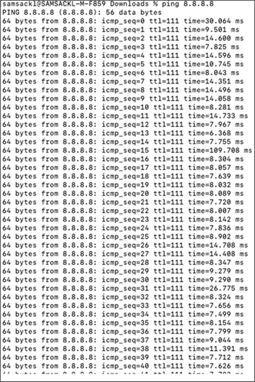
| Note: No impact on traffic flow for wireless clients |
Introducing Loops (Access Layer, with STP Guard: Loop Guard)
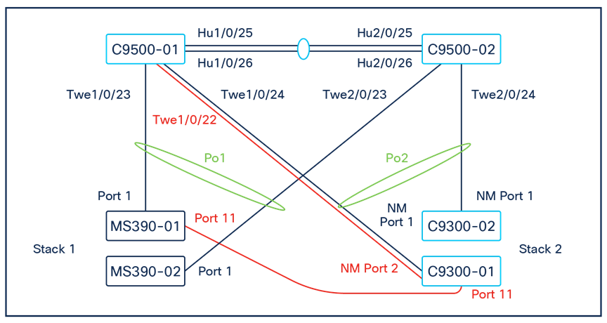
For the purposes of this test and in addition to the previous loop connections, the following ports were connected: MS390-01 / Port 11 < - > C9300-01 / Port 11
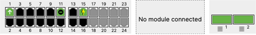
| Note: Port 11 on MS390-01 in STP BLK state |
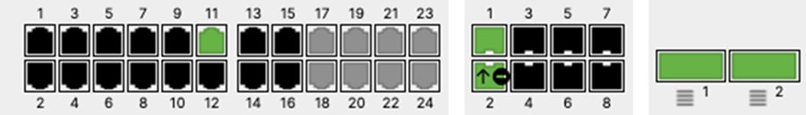
| Note: Port 11 on C9300-01 in STP FWD state (Bridge ID: 61440:a4b4.395f.2a8b) |

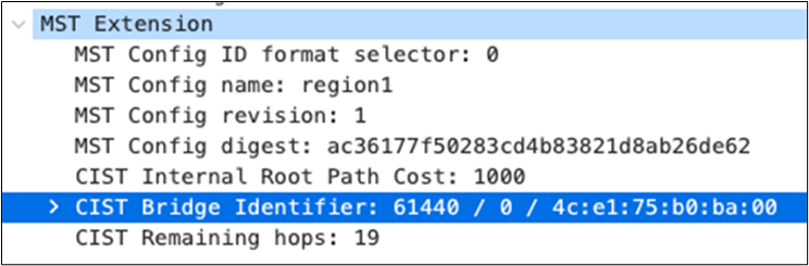
| Note: Packet capture on MS390-01 / Port 11 shows that Bridge ID: 61440:4ce1.75b0.ba00 is relaying the Root bridge BPDUs with Root Bridge ID: 4096:b0c5.3c60.fba0 |
Introducing Loops (Access Layer, without STP Guard)

For the purposes of this test and in addition to the previous loop connections, the following ports were connected:
MS390-02 / Port 12 < - > C9300-02 / Port 12
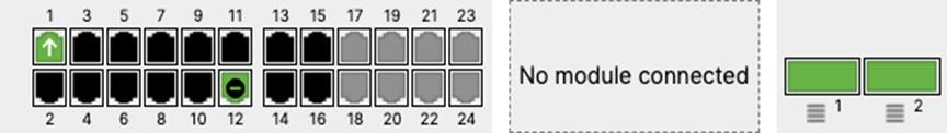
| Note: MS390-02 / Port 12 is in STP BLK state (Bridge ID: 61440:2c3f.0b0f.ec00) |
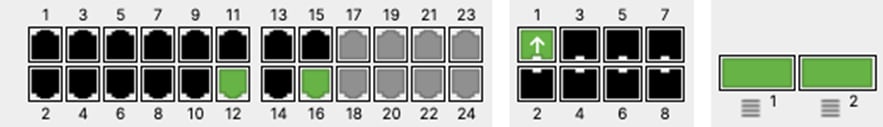
| Note: C9300-02 / Port 12 is in STP FWD state (Bridge ID: 61440:4ce1.75b0.ba00) |
Introducing Loops (Core Layer)

For the purpose of this test and in addition to the previous loop connections, the following ports were connected:
Port Twe1/0/10 to port Twe2/0/10 on the C9500 Core switches.
| 9500-01#show run interface Twe1/0/10 Building configuration... Current configuration : 132 bytes ! interface TwentyFiveGigE1/0/10 switchport trunk allowed vlan 1,10,20,30,40 switchport mode trunk spanning-tree guard root end 9500-01#show run interface Twe2/0/10 Building configuration... Current configuration : 132 bytes ! interface TwentyFiveGigE2/0/10 switchport trunk allowed vlan 1,10,20,30,40 switchport mode trunk spanning-tree guard root end 9500-01# 9500-01#show ip interface brief | in TwentyFiveGigE1/0/10 TwentyFiveGigE1/0/10 unassigned YES unset up up 9500-01# 9500-01#show ip interface brief | in TwentyFiveGigE2/0/10 TwentyFiveGigE2/0/10 unassigned YES unset up up 9500-01#show spanning-tree MST0 Spanning tree enabled protocol mstp Root ID Priority 4096 Address b0c5.3c60.fba0 This bridge is the root Hello Time 2 sec Max Age 20 sec Forward Delay 15 sec Bridge ID Priority 4096 (priority 4096 sys-id-ext 0) Address b0c5.3c60.fba0 Hello Time 2 sec Max Age 20 sec Forward Delay 15 sec
Interface Role Sts Cost Prio.Nbr Type ------------------------------------------------ Twe1/0/1 Desg FWD 2000 128.193 P2p Twe1/0/2 Desg FWD 2000 128.194 P2p Twe1/0/10 Desg BLK 2000 128.202 P2p Twe1/0/22 Desg FWD 2000 128.214 P2p Twe2/0/1 Back BLK 2000 128.385 P2p Twe2/0/2 Back BLK 2000 128.386 P2p Twe2/0/10 Desg BKN*2000 128.394 P2p *ROOT_Inc Po1 Desg FWD 10000 128.2089 P2p Po2 Desg FWD 1000 128.2090 P2p
9500-01#show spanning-tree interface Twe2/0/10 detail Port 394 (TwentyFiveGigE2/0/10) of MST0 is broken (Root Inconsistent) Port path cost 2000, Port priority 128, Port Identifier 128.394. Designated root has priority 4096, address 4ce1.75b0.ba00 Designated bridge has priority 8192, address b0c5.3c60.fba0 Designated port id is 128.394, designated path cost 0 Timers: message age 4, forward delay 0, hold 0 Number of transitions to forwarding state: 0 Link type is point-to-point by default, Internal PVST Simulation is enabled by default Root guard is enabled on the port BPDU: sent 2592, received 5175 9500-01# |
Introducing Rogue Bridge in VLAN 1
For the purpose of this test and in addition to the previous loop connections, the Bridge priority on C9300 Stack will be reduced to 4096 (likely root) and increasing the Bridge priority on C9500 to 8192.
● Downlinks on C9500 are configured with STP Root Guard
● Access Layer Links (Stack to Stack) are configured with STP Loop Guard + UDLD
| 9500-01(config)#spanning-tree mst 0 priority 8192 9500-01(config)#end 9500-01#show spanning-tree MST0 Spanning tree enabled protocol mstp Root ID Priority 8192 Address b0c5.3c60.fba0 This bridge is the root Hello Time 2 sec Max Age 20 sec Forward Delay 15 sec Bridge ID Priority 8192 (priority 8192 sys-id-ext 0) Address b0c5.3c60.fba0 Hello Time 2 sec Max Age 20 sec Forward Delay 15 sec
Interface Role Sts Cost Prio.Nbr Type Twe1/0/1 Desg FWD 2000 128.193 P2p Twe1/0/10 Desg FWD 2000 128.202 P2p Twe1/0/22 Desg FWD 2000 128.214 P2p Twe2/0/1 Back BLK 2000 128.385 P2p Twe2/0/10 Desg BKN*2000 128.394 P2p *ROOT_Inc Po1 Desg FWD 10000 128.2089 P2p Po2 Desg FWD 1000 128.2090 P2p 9500-01# |
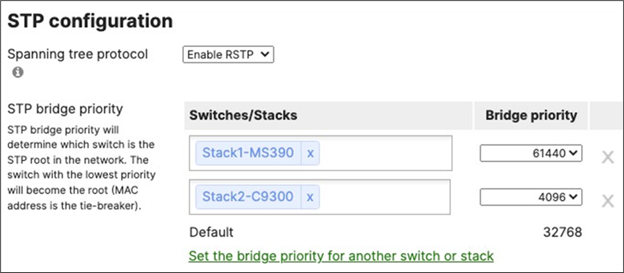
| 9500-01#show spanning-tree MST0 Spanning tree enabled protocol mstp Root ID Priority 8192 Address b0c5.3c60.fba0 This bridge is the root Hello Time 2 sec Max Age 20 sec Forward Delay 15 sec Bridge ID Priority 8192 (priority 8192 sys-id-ext 0) Address b0c5.3c60.fba0 Hello Time 2 sec Max Age 20 sec Forward Delay 15 sec
Interface RoleSts Cost Prio.Nbr Type -------------------------------------------------------- Twe1/0/1 Desg FWD 2000 128.193 P2p Twe1/0/2 Desg FWD 2000 128.194 P2p Twe1/0/10 Desg FWD 2000 128.202 P2p Twe1/0/22 Desg BKN*2000 128.214 P2p *ROOT_Inc Twe2/0/1 Back BLK 2000 128.385 P2p Twe2/0/2 Back BLK 2000 128.386 P2p Twe2/0/10 Desg BKN*2000 128.394 P2p *ROOT_Inc Po1 Desg FWD 10000 128.2089 P2p Po2 Desg FWD 1000 128.2090 P2p
9500-01# 9500-01#show spanning-tree interface Twe1/0/22 detail Port 214 (TwentyFiveGigE1/0/22) of MST0 is broken (Root Inconsistent) Port path cost 2000, Port priority 128, Port Identifier 128.214. Designated root has priority 4096, address 4ce1.75b0.ba00 Designated bridge has priority 8192, address b0c5.3c60.fba0 Designated port id is 128.214, designated path cost 0 Timers: message age 5, forward delay 0, hold 0 Number of transitions to forwarding state: 2 Link type is point-to-point by default, Internal PVST Simulation is enabled by default Root guard is enabled on the port BPDU: sent 4611, received 319 9500-01# |
| Note: C9500 Core Stack is still the Root Bridge (i.e. The root Bridge placement has been enforced). |

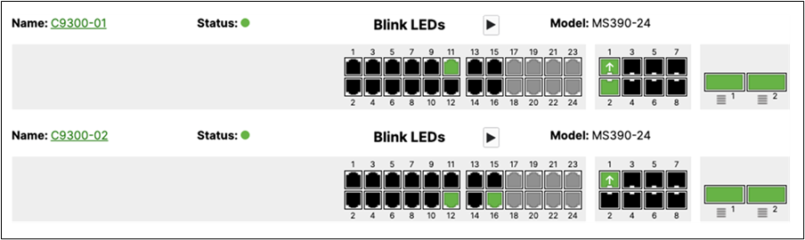
| Note: C9300 Stack is root |
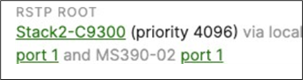
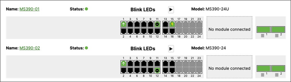
| Note: C9300 Stack is root for MS390 |

| Note: Wireless client traffic flow disrupted for about 30 secs |
| Notes: Reverting all configuration back to original state: 1. Disconnect and shutdown interface TwentyFiveGigE1/0/22 2. Disconnect port 11 on MS390-01 and C9300-01 and remove Loop Guard and UDLD 3. Disconnect port 12 on MS390-02 and C9300-02. 4. Disconnect and revert port TwentyFiveGigE1/0/10 and TwentyFiveGigE20/10 back to access with VLAN 1 and shutdown 5. Change MST priority on C9300 stack to 61440 6. Change MST priority on C9500 Core Stack to 4096 |
High Availability and Failover
Here's the steady-state physical architecture for reference:
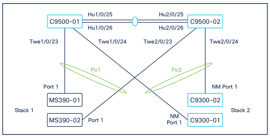
MX WAN Edge Failover
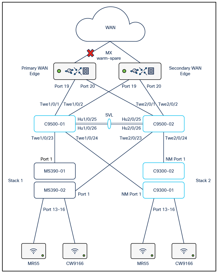

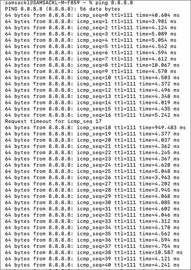
| Note: Client traffic was very briefly disrupted during failover event (1 packet drop) |

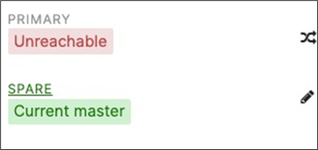
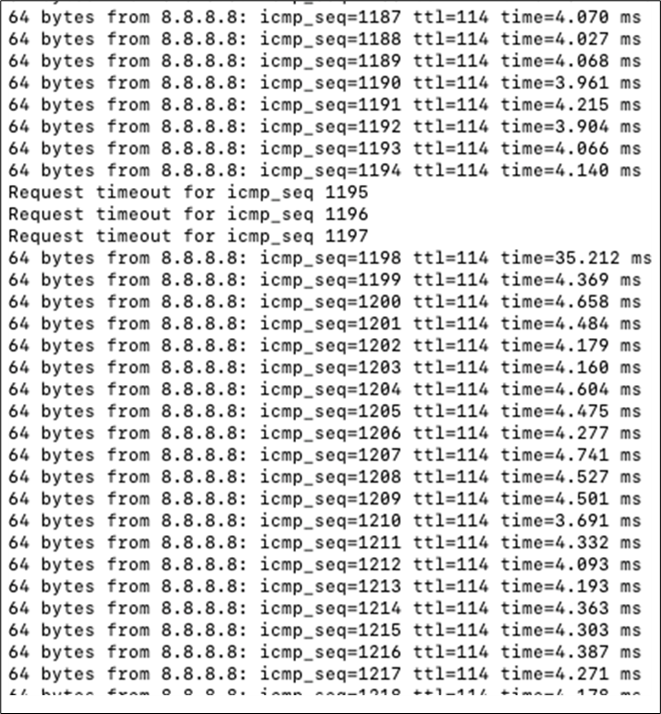
| Note: Client traffic disrupted for about 1-3 secs |
C9500 Core Stack Loss of Uplink
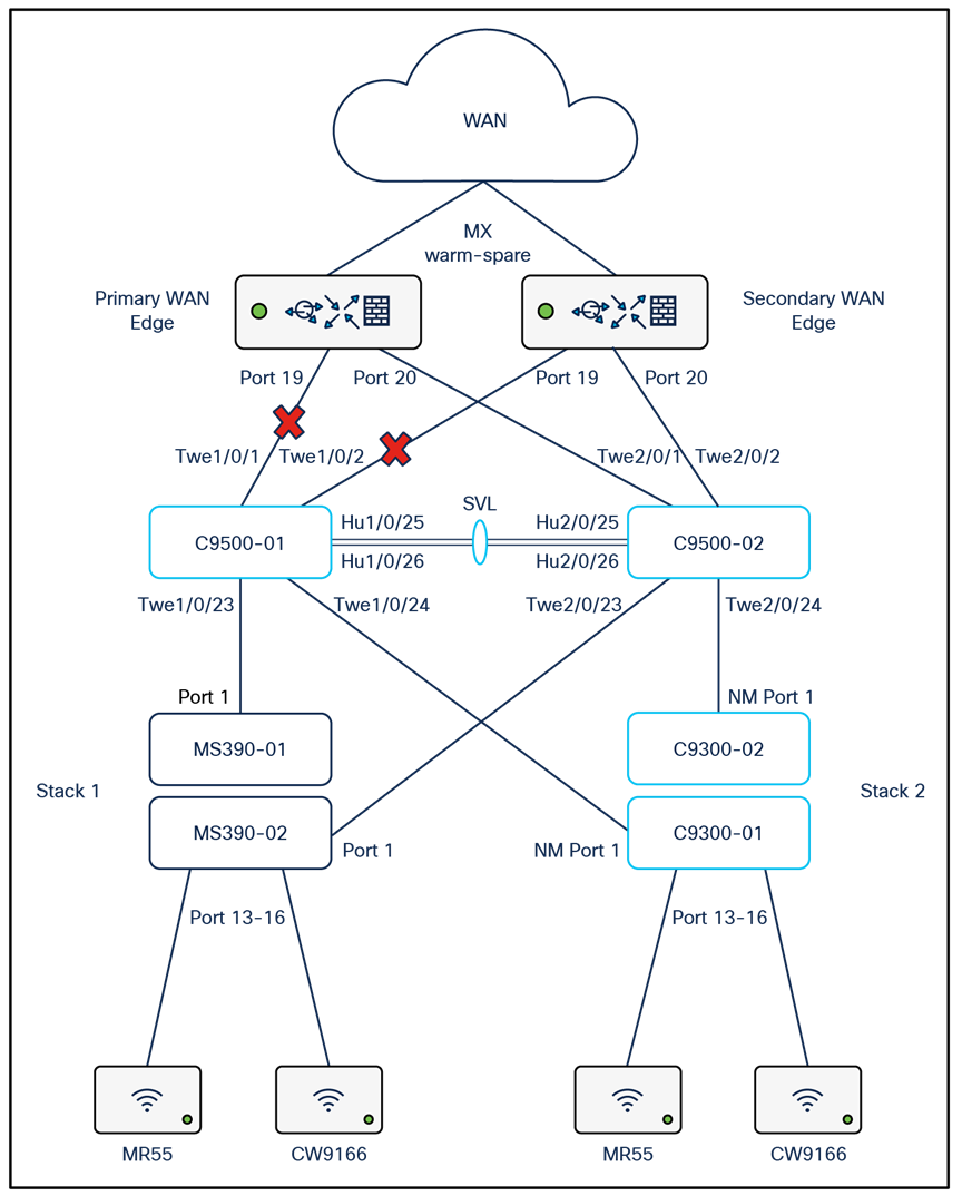
For the purpose of this test, ports TwentyFiveGigE1/0/1 and TwentyFiveGigE1/0/2 will be disconnected.
| 9500-01#show ip interface brief TwentyFiveGigE1/0/1 unassigned YES unset down down TwentyFiveGigE1/0/2 unassigned YES unset down down TwentyFiveGigE2/0/1 unassigned YES unset up up TwentyFiveGigE2/0/2 unassigned YES unset up up 9500-01#show switch Switch/Stack Mac Address : b0c5.3c60.fba0 - Local Mac Address Mac persistency wait time: Indefinite H/W Current
Switch# Role Mac Address Priority Version State ------------------------------------------------------------------- *1 Active b0c5.3c60.fba0 5 V02 Ready 2 Standby 40b5.c111.01e0 1 V02 Ready
9500-01# |

| Note: Wireless client traffic flow disrupted for about 30 secs |
C9300 Stack Loss of Uplink
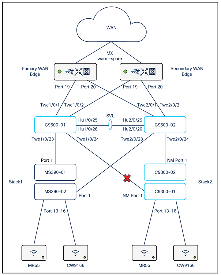
For the purpose of this test, NM Port 1 on C9300-01 (Master switch) will be disconnected.
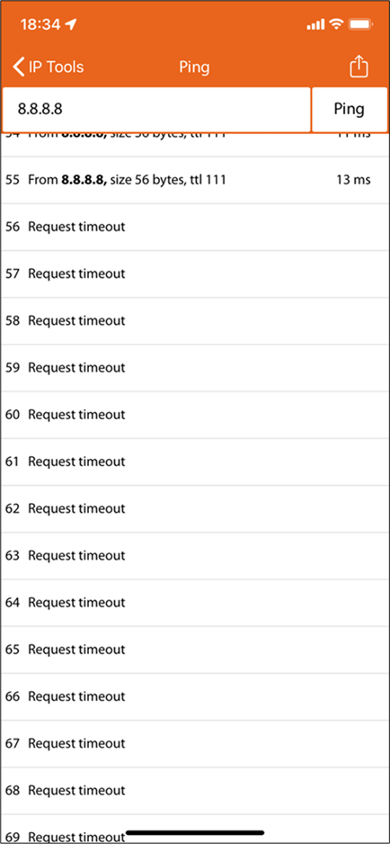
| Note: Wireless client traffic flow disrupted for about 30 secs |
MS390 Stack Loss of Uplink

For the purpose of this test, port 1 on MS390-01 (Master switch) will be disconnected.
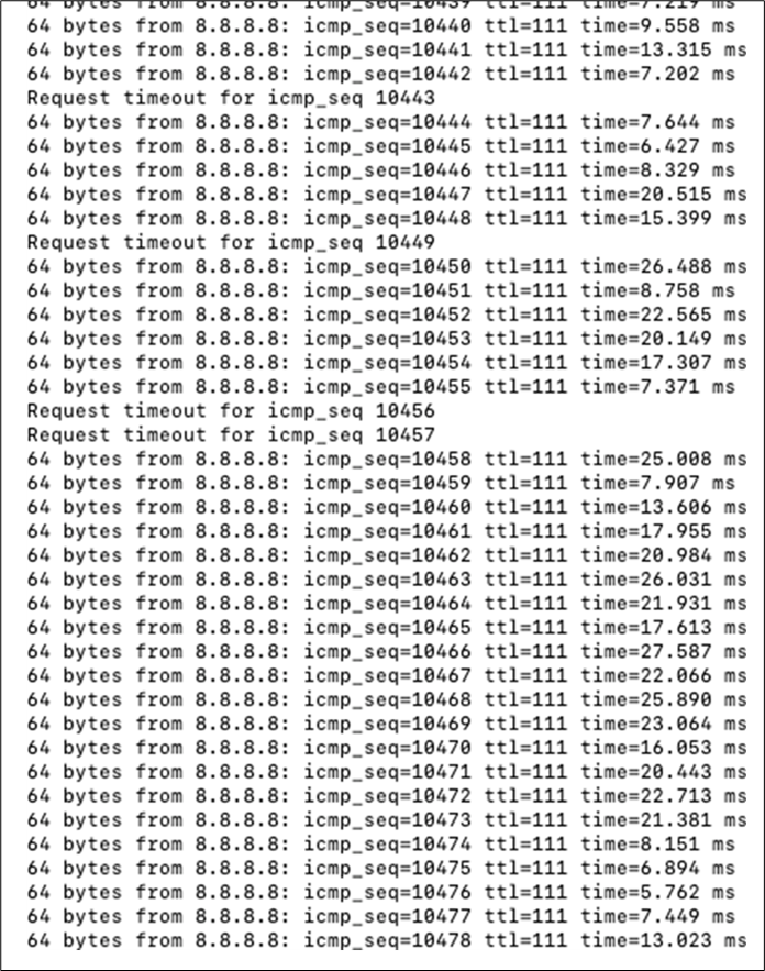
| Note: Wireless client traffic to the internet disrupted for about 2 secs |
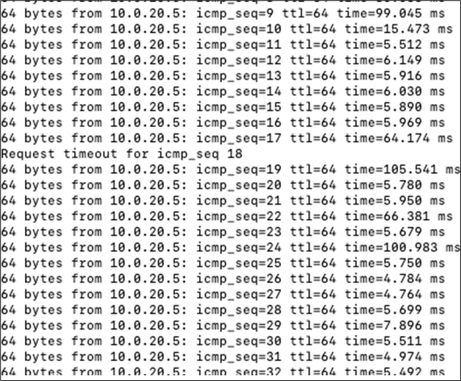
| Note: Wireless client traffic on Campus LAN disrupted for about 1 sec |
QoS
For the purpose of this test, packet capture will be taken between two clients running a Webex session. Packet capture will be taken on the Edge (i.e. MR wireless and wired interfaces) then on the Access (i.e. the MS390 or C9300 uplink port) then on the MX WAN Downlink and finally on the MX WAN Uplink. The table below shows the testing components and the expected QoS behavior:
| Client |
Application |
Access Point (Wired) Expected QoS |
Access Switch Uplink Port Expected QoS |
MX Appliance Uplink Port Expected QoS |
| Client #1 (10.0.20.2) iPhone 11 (cc:66:0a:3e:44:69) |
Webex (UDP 9000) |
AP3_Zone2 / AF41 / DSCP 34 |
C9300-02 (Port 25) / AF41 / DSCP 34 |
AF41 / DSCP 34 |
| iTunes |
AP3_Zone2 / AF21 / DSCP 18 |
C9300-02 (Port 25) / AF21 / DSCP 18 |
AF21 / DSCP 18 |
|
| Client #2 (10.0.20.3) MacBook Pro (3c:22:fb:30:da:69) |
Webex (UDP 9000) |
AP2_Zone1 / AF41 / DSCP 34 |
MS390-01 (Port 1) / AF41 / DSCP 34 |
AF41 / DSCP 34 |
| Dropbox |
AP2_Zone1 / AF0 / DSCP 0 |
MS390-01 (Port 1) / AF0 / DSCP 0 |
AF0 / DSCP 0 |
Access Point Wireless Port pcaps
Client #1
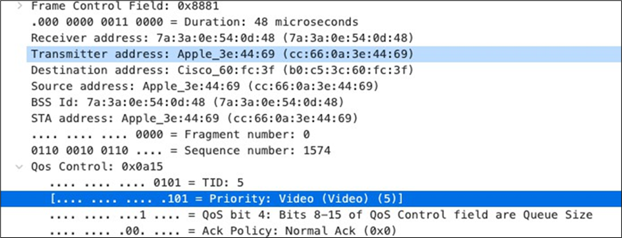
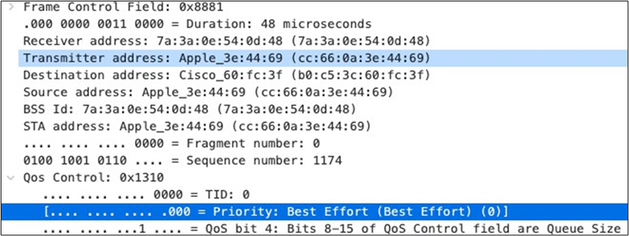
| Note: Please note that QoS values in this case could be arbitrary as they are upstream (i.e. Client to AP) unless you have configured Wireless Profiles on the client devices. Please check the following article for more details on creating Wireless Profiles and using FastLane with Meraki Systems Manager. |
Client #2
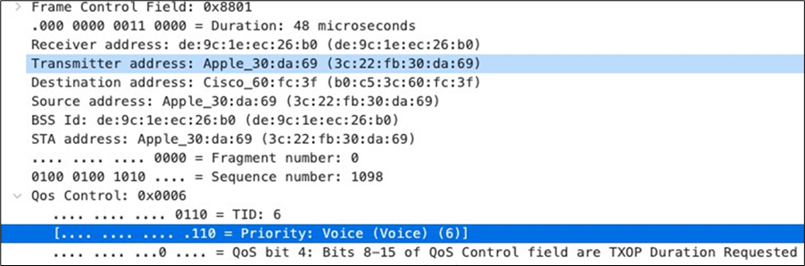
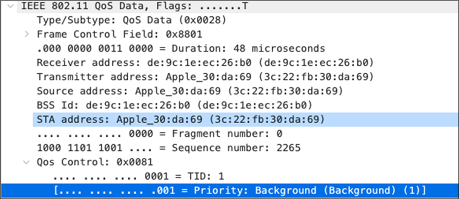
| Note: Please note that QoS values in this case could be arbitrary as they are upstream (i.e. Client to AP) unless you have configured Wireless Profiles on the client devices. Please check the following article for more details on creating Wireless Profiles and using FastLane with Meraki Systems Manager. |
Access Point Wired Port pcaps
Client #1
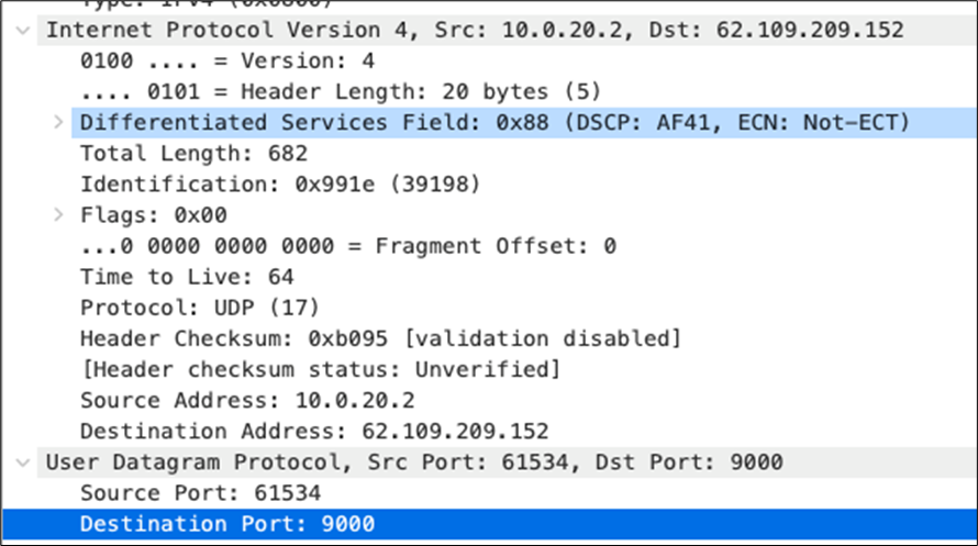
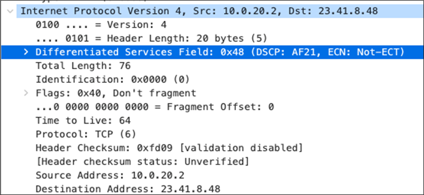
Client #2
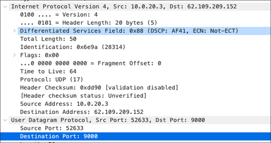
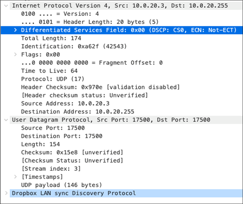
Access Switch Uplink pcaps
Client #1
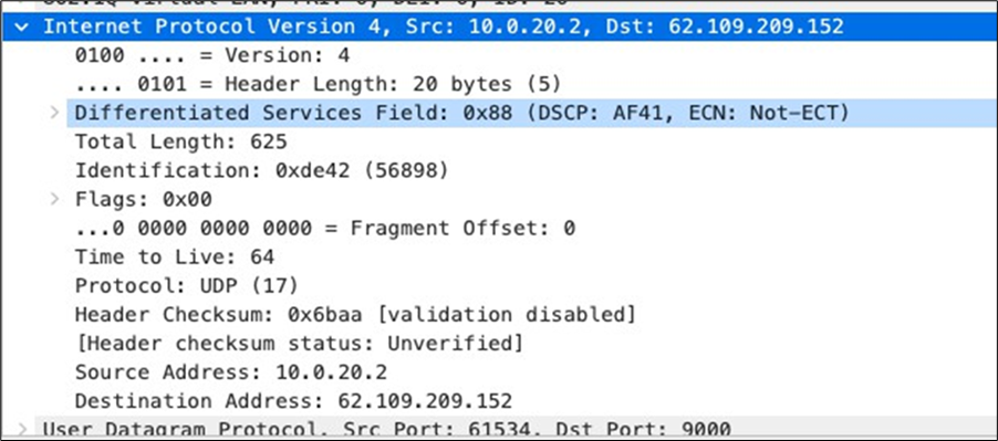
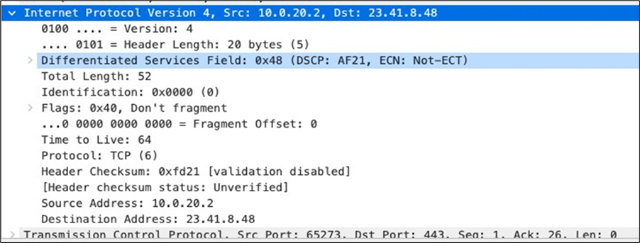
Client #2
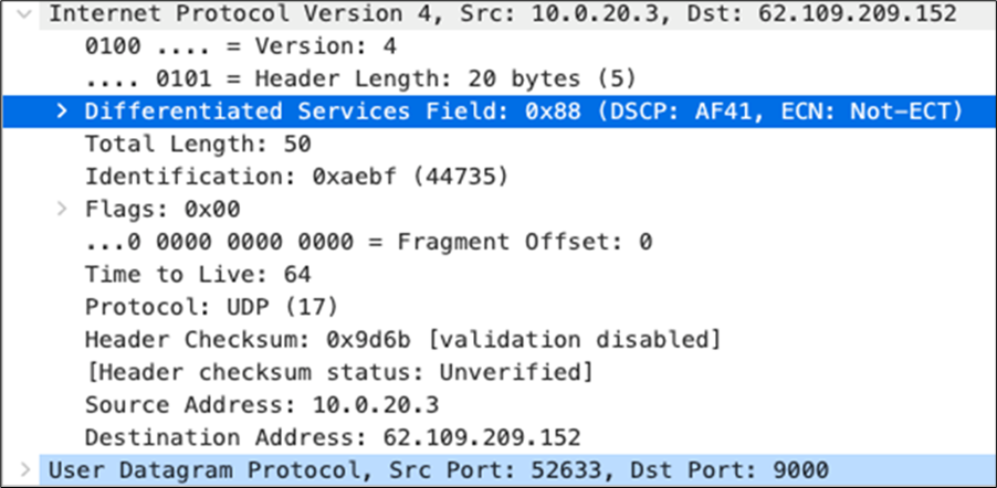
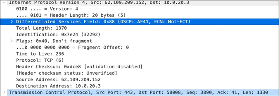
MX appliance Downlink pcaps
Client #1
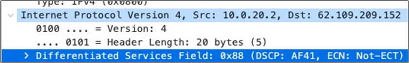
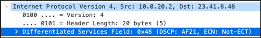
Client #2
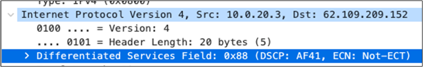
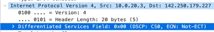
MX Appliance Uplink pcaps
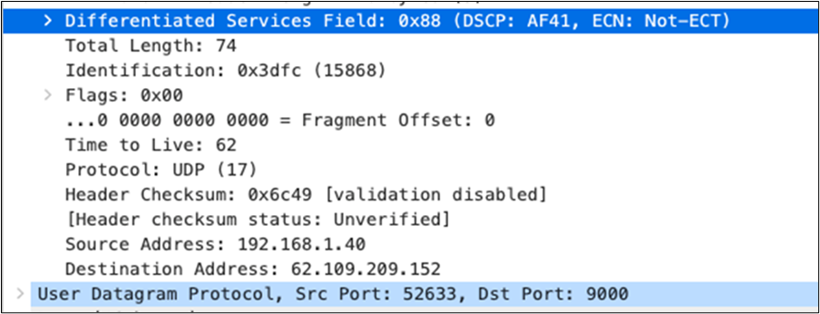
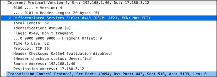
Option 2: STP-Based Convergence without Native VLAN 1
Overview
This option is similar to the above except that the default VLAN 1 does not exist and the Native VLAN is replaced with another non-trivial VLAN assignment which can be considered a more preferable option for customers as it's separate from the Management VLAN. Also, a Transit VLAN has been introduced between the C9500 Core Stack and the MX WAN Edge to facilitate the separation between Management traffic (VLAN 100) and Client Traffic (Transit VLAN 192)
This design is based on consistent STP protocols running in this campus deployment, as such Multiple Spanning Tree Protocol (MST, aka 802.1s) will be configured since it is supported on both the Meraki and Catalyst platforms.
| Tech Tip: It is recommended to run the same STP protocol across all switches (MST in this case). Running any other protocol on Catalyst (e.g. PVST) can introduce undesired behavior and can be more difficult to troubleshoot. |
| Tech Tip: Running PVST/PVST+ on Catalyst in this design will result in very slow STP convergence and create an inconsistent STP domain due to the fact that PVST/PVST+ backward compatible BPDUs only run in VLAN 1 tagged whereas Meraki switches will send 802.1D BPDUs in the Native VLAN untagged |
You should consider this option if you need to steer away from having VLAN 1 in your Campus LAN. Here's some things to consider about this design option:
Pros:
● Flexibility in your VLAN design
● Facilitates Wireless Roaming across the whole campus
● Easier to deploy and consistent configuration across the entire Campus LAN
● Minimize the risk of VLAN hopping
● Considered more secure due to separation between Management traffic and Client traffic
Cons:
● Non-deterministic route failover
● Slow convergence
● Different STP protocols on Cloud Managed and Cloud Monitored Catalyst Switches
| Tech Tip: Since STP will be used as a loop prevention mechanism, all SVIs will be created on the collapsed core layer with the exception of the Management (aka Infrastructure VLAN) and Transit VLAN. |
Logical Architecture
The following diagram shows the logical architecture highlighting STP convergence within a campus LAN design leveraging Cloud Managed and Cloud Monitored Catalyst platforms:

Physical Architecture
The following diagram shows the physical architecture and port list for this design:

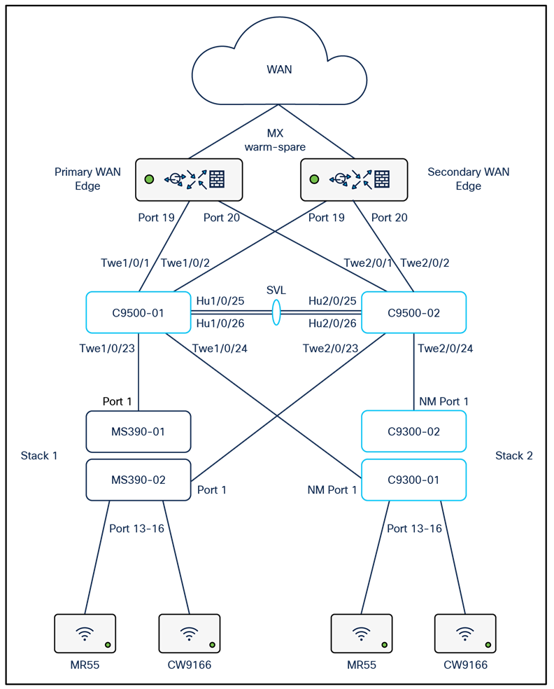
Assumptions
The following assumptions have been considered:
● VLAN 1 should not be configured on any switchport in this Campus LAN
● It is assumed that Wireless roaming is required everywhere in the Campus
● It is assumed that VLANs are spanning across multiple zones
● Corporate SSID (Broadcast in all zones) users are assigned VLAN 10 on all APs. CoA VLAN is VLAN 30 (Via Cisco ISE)
● BYOD SSID (Broadcast in all zones) users are assigned VLAN 20 on all APs. CoA VLAN is VLAN 30 (Via Cisco ISE)
● Guest SSID (Broadcast in all zones) users are assigned VLAN 30 on all APs
● IoT SSID (Broadcast in all zones) users are assigned VLAN 40 on all APs
● Access Switches will be running in Layer 2 mode (No SVIs or DHCP)
● MS390-M Access Switches physically stacked together
● C9300-M Access Switches physically stacked together
● C9500 Core Switches with Stackwise-virtual stacking using SVLs
● Access Switch uplinks are in trunk mode with native VLAN = VLAN 1 (Management VLAN*)
● STP root is at Distribution/Collapsed-core
● Distribution/Collapsed-core uplinks are in Trunk mode with Native VLAN = VLAN 1 (Management VLAN)
● All VLAN SVIs are hosted on the core layer
● Network devices will be assigned fixed IPs from the management VLAN DHCP pool. Default Gateway is 10.0.100.1
Network Segments
Please check the following table for more information about the network segments (e.g. VLANs, SVIs, etc.) for this design:
| Network Segment |
VLAN ID |
Subnet |
Default Gateway |
Notes |
| Infrastructure |
100 |
10.0.100.0/24 |
10.0.100.1 |
SVI hosted on edge MX |
| Transit |
192 |
192.168.0.0/24 |
192.168.0.1 |
SVI hosted on edge MX |
| Corporate Devices (Wireless and Wired) |
10 |
10.0.10.0/24 |
10.0.10.1 |
SVI hosted on core switches |
| BYOD Wireless Devices |
20 |
10.0.20.0/24 |
10.0.20.1 |
SVI hosted on core switches |
| Guest Wireless Devices |
30 |
10.0.30.0/24 |
10.0.30.1 |
SVI hosted on core switches |
| IoT Wireless Devices |
40 |
10.0.40.0/24 |
10.0.40.1 |
SVI hosted on core switches |
| Tech Tip: Please size your subnets based on your own requirements. The above table is for illustration purposes only |
| Tech Tip: In this example, the Infrastructure VLAN has been created on the Edge MX. Alternatively, you can create the SVI on the C9500 Core Stack |
Quality of Service
| Application |
MR |
Access Switches |
Core Switches |
| SIP (Voice) |
EF DSCP 46 AC_Vo |
Trust incoming values DSCP 46 CoS 5 |
Trust incoming values |
| Webex and Skype |
AF41 DSCP 34 AC_VI |
Trust incoming values DSCP 34 CoS 4 |
Trust incoming values |
| All Video and Music |
AF21 DSCP 18 AC_BE |
Trust incoming values DSCP 18 CoS 2 |
Trust incoming values |
| Software Updates |
AF11 DSCP 10 AC_BK |
Trust incoming values DSCP 10 CoS 1 |
Trust incoming values |
| Tech Tip: Please note that the above table is for illustration purposes only. Please configure QoS based on your network requirements. Refer to the following articles for more information on traffic shaping and QoS settings on Meraki devices: |
Device list
| Device |
Name |
Management IP address |
Notes |
||||
| MX250 MX250 |
Primary WAN Edge Spare WAN Edge |
10.0.100.1 |
warm-spare |
||||
| C9500-24YCY C9500-24YCY |
C9500-01 C9500-02 |
10.0.100.2 |
Stackwise Virtual (C9500-Core-Stack) |
||||
| MS390-24P MS390-24P |
MS390-01 MS390-02 |
10.0.100.3 |
Physical Stacking (Stack1-MS390) |
||||
| C9300-24P C9300-24P |
C9300-01 C9300-02 |
100.100.4 |
Physical Stacking (Stack2-C9300) |
||||
| MR55 |
AP1_Zone1 |
10.0.100.5 |
Tag = Zone1 |
||||
| C9166 (eq MR57) |
AP2_Zone1 |
10.0.100.6 |
Tag = Zone1 |
||||
| MR55 |
AP3_Zone2 |
10.0.100.7 |
Tag = Zone2 |
||||
| C9166 (eq MR57) |
AP4_Zone2 |
10.0.100.8 |
Tag = Zone2 |
Access policies
| Access Policy Name |
Purpose |
Configuration |
Notes |
| Wired-1x |
802.1x Authentication via Cisco ISE for wired clients that support 802.1x |
Authentication method = my Radius server Radius CoA = enabled Host mode = Single-Host Access Policy type = 802.1x Guest VLAN = 30 Failed Auth VLAN = 30 Critical Auth VLAN = 30 Suspend Port Bounce = Enabled Voice Clients = Bypass authentication Walled Garden = enabled |
Cisco ISE authentication and posture checks |
| Wired-MAB |
MAB Authentication via Cisco ISE for wired clients that do not support 802.1x |
Authentication method = my Radius server Radius CoA = disabled Host mode = Single-Host Access Policy type = MAC authentication bypass Guest VLAN = 30 Failed Auth VLAN = 30 Critical Auth VLAN = 30 Suspect Port Bounce = Enabled Voice Clients = Bypass authentication Walled Garden = disabled |
Cisco ISE authentication |
Port list
| Device name |
Port |
Far-end |
Port details |
Notes |
|
| Primary WAN Edge / Spare WAN Edge |
1 |
WAN1 |
|
VIP1 |
|
| Primary WAN Edge / Spare WAN Edge |
2 |
WAN2 |
|
VIP2 |
|
| Primary WAN Edge |
19 |
9500-01 (PortTwe1/0/1) |
Trunk (Native VLAN 100) Allowed VLANs 100, 192 |
Downlink |
|
| 20 |
9500-02 (PortTwe2/0/1) |
Trunk (Native VLAN 100) Allowed VLANs 100, 192 |
Downlink |
||
| Spare WAN Edge |
19 |
9500-01 (Port Twe1/0/2) |
Trunk (Native VLAN 100) Allowed VLANs 100, 192 |
Downlink |
|
| 20 |
9500-02 (Port Twe2/0/2) |
Trunk (Native VLAN 100) Allowed VLANs 100, 192 |
Downlink |
||
| 9500-01 |
Twe1/0/1 |
Primary WAN Edge (Port 19) |
switchport mode trunk switchport trunk native vlan 100 switchport trunk allowed vlan 100,192 |
Uplink |
|
| Twe1/0/2 |
Spare WAN Edge (Port 19) |
switchport mode trunk switchport trunk native vlan 100 switchport trunk allowed vlan 100,192 |
Uplink |
||
| 9500-02 |
Twe2/0/1 |
Primary WAN Edge (Port 20) |
switchport mode trunk switchport trunk native vlan 100 switchport trunk allowed vlan 100,192 |
Uplink |
|
| Twe2/0/2 |
Spare WAN Edge (Port 20) |
switchport mode trunk switchport trunk native vlan 100 switchport trunk allowed vlan 100,192 |
Uplink |
||
| 9500-01 |
Twe1/0/23 |
MS390-01 (Port 1) |
switchport mode trunk switchport trunk native vlan 100 switchport trunk allowed vlans 10,20,30,40, 100 channel-group 1 mode active spanning-tree guard root auto qos trust dscp policy static sgt 2 trusted |
Downlink |
|
| Twe1/0/24 |
C9300-01 (Port 1) |
switchport mode trunk switchport trunk native vlan 100 switchport trunk allowed vlans 10,20,30,40,100 channel-group 2 mode active spanning-tree guard root auto qos trust dscp policy static sgt 2 trusted |
Downlink |
||
| 9500-02 |
Twe2/0/23 |
MS390-02 (Port 1) |
switchport mode trunk switchport trunk native vlan 100 switchport trunk allowed vlans 10,20,30,40,100 channel-group 1 mode active spanning-tree guard root auto qos trust dscp policy static sgt 2 trusted |
Downlink |
|
| Twe2/0/24 |
C9300-02 (Port 1) |
switchport mode trunk switchport trunk native vlan 100 switchport trunk allowed vlans 10,20,30,40,100 channel-group 2 mode active spanning-tree guard root auto qos trust dscp policy static sgt 2 trusted |
Downlink |
||
| 9500-01 |
Hu1/0/25 |
C9500-02 (Port Hu2/0/26) |
stackwise-virtual link 1 |
Stackwise Virtual |
|
| Hu1/0/26 |
C9500-02 (Port Hu2/0/25) |
stackwise-virtual link 1 |
Stackwise Virtual |
||
| 9500-02 |
Hu2/0/25 |
C9500-01 (PortHu1/0/26) |
stackwise-virtual link 1 |
Stackwise Virtual |
|
| Hu2/0/26 |
C9500-01 (PortHu1/0/25) |
stackwise-virtual link 1 |
Stackwise Virtual |
||
| MS390-01 |
5-8 |
Wired Clients |
Access (Data VLAN 10) Access Policy = Wired-1x PoE Enabled STP BPDU Guard Tag = Wired Clients 802.1x AdP: Corp |
For wired clients supporting 802.1x |
|
| MS390-02 |
|||||
| C9300-01 |
|||||
| C9300-02 |
|||||
| MS390-01 |
9-12 |
Wired Clients |
Access (Data VLAN 10) Access Policy = MAB PoE Enabled STP BPDU Guard Tag = Wired Clients MAB AdP: Corp |
For wired clients that do not support 802.1x |
|
| MS390-02 |
|||||
| C9300-01 |
|||||
| C9300-02 |
|||||
| MS390-01 |
13-16 |
MR |
Trunk (Native VLAN 100) PoE Enabled STP BPDU Guard Tag = MR WLAN Peer SGT Capable AdP: Infrastructure |
Allowed VLANs: 10,20,30,40,100 |
|
| MS390-02 |
|||||
| C9300-01 |
|||||
| C9300-02 |
|||||
| MS390-01 |
1 |
9500-01 (Port Twe1/0/23) |
Trunk (Native VLAN 100) PoE Disabled Name: Core 1 Tag = Uplink Peer SGT Capable AdP: Infrastructure |
Allowed VLANs: 10,20,30,40,100 |
|
| MS390-02 |
1 |
9500-02 (Port Twe2/0/23) |
Trunk (Native VLAN 100) PoE Disabled Name: Core 2 Tag = Uplink Peer SGT Capable AdP: Infrastructure |
Allowed VLANs: 10,20,30,40,100 |
|
| C9300-01 |
C9300-01 / C9300-NM-8X / 1 |
9500-01 (Port Twe1/0/24) |
Trunk (Native VLAN 100) PoE Disabled Name: Core 1 Tag = Uplink Peer SGT Capable AdP: Infrastructure |
Allowed VLANs: 10,20,30,40,100 |
|
| C9300-02 |
C9300-02 / C9300-NM-8X / 1 |
C9500-02 (Port Twe2/0/24) |
Trunk (Native VLAN 100) PoE Disabled Name: Core 2 Tag = Uplink Peer SGT Capable AdP: Infrastructure |
Allowed VLANs: 10,20,30,40,100 |
|
Wireless SSID list
| SSID Name |
Broadcast |
Configuration |
Notes |
Firewall and Traffic Shaping |
|
| Acme Corp |
All APs |
Association = Enterprise with my Radius server Encryption = WPA2 only Splash Page = Cisco ISE Radius CoA = Enabled SSID mode = Bridge mode VLAN Tagging = 10 (ISE Override) AdP Group = 10:Corp Radius override = Enabled Mandatory DHCP = Enabled Layer 2 isolation = Disabled Allow Clients access LAN = Allow Traffic Shaping = Enabled with default settings |
Cisco ISE Authentication and posture checks (172.31.16.32/1812) |
Layer 2 Isolation = Disabled Allow Access to LAN = Enabled Per-Client Bandwidth Limit = 50Mbps Per-SSID Bandwidth Limit = Unlimited Enable Default Traffic Shaping rules SIP - EF (DSCP 46) Software Updates - AF11 (DSCP 10) Webex and Skype - AF41 (DSCP 34) All Video and Music - AF21 (DSCP 18) |
|
| Acme BYOD |
All APs |
Association = Enterprise with my Radius server Encryption = WPA2 only 802.11w = Enabled Splash Page = Cisco ISE SSID mode = Bridge mode VLAN Tagging = 20 AdP Group = 20:BYOD Radius override = Disabled Mandatory DHCP = Enabled Layer 2 isolation = Disabled Allow Clients access LAN = Allow Traffic Shaping = Enabled with default settings |
Cisco ISE Authentication (via Azure AD) and posture checks. Dynamic GP assignment (Radius attribute = Airospace-ACLNAME) |
Layer 2 Isolation = Disabled Allow Access to LAN = Enabled Per-Client Bandwidth Limit = 50Mbps Per-SSID Bandwidth Limit = Unlimited Enable Default Traffic Shaping rules SIP - EF (DSCP 46) Software Updates - AF11 (DSCP 10) Webex and Skype - AF41 (DSCP 34) All Video and Music - AF21 (DSCP 18) |
|
| Guest |
All APs |
Association = Enterprise with my Radius server Encryption = WPA1 and WPA2 802.11w = Enabled Splash Page = Click-Through SSID mode = Bridge mode VLAN Tagging = 30 AdP Group = 30:Guest Radius override = Disabled Mandatory DHCP = Enabled Layer 2 isolation = Enabled Allow Clients access LAN = Deny Per SSID limit = 100Mbps Traffic Shaping = Enabled with default settings |
Meraki Authentication |
Layer 2 Isolation = Enabled Allow Access to LAN = Disabled Per-Client Bandwidth Limit = 5Mbps Per-SSID Bandwidth Limit = 100Mbps Enable Default Traffic Shaping rules SIP - EF (DSCP 46) Software Updates - AF11 (DSCP 10) Webex and Skype - AF41 (DSCP 34) All Video and Music - AF21 (DSCP 18) |
|
| Acme IoT |
All APs |
Association = identity PSK with Radius Encryption = WPA1 and WPA2 802.11r = Disabled 802.11w = Disabled Splash Page = None Radius CoA = Disabled SSID mode = Bridge mode VLAN Tagging = 40 AdP Group = 40:IoT Radius override = Disabled Mandatory DHCP = Enabled Allow Clients access LAN = Deny Per SSID limit = 10Mbps Traffic Shaping = Enabled with default settings |
Cisco ISE is queried at association time to obtain a passphrase for a device based on its MAC address. Dynamic GP assignment (Radius attribute Filter-Id) |
Layer 2 Isolation = Disabled Allow Access to LAN = Enabled Per-Client Bandwidth Limit = 5Mbps Per-SSID Bandwidth Limit = Unlimited Enable Default Traffic Shaping rules SIP - EF (DSCP 46) Software Updates - AF11 (DSCP 10) Webex and Skype - AF41 (DSCP 34) All Video and Music - AF21 (DSCP 18) |
|
| Tech Tips:
● The above configuration is for illustration purposes only. Please configure your SSIDs based on your own requirements (mode, IP assignment, etc.)
● Please note that Adaptive Policy on MR requires MR-ADV license. For more information about the requirements, please refer to this
document.
|
Configuration and implementation guidelines
The following section will take you through the steps to amend your design by removing VLAN 1 and creating the desired new Native VLAN (e.g. VLAN 100) across your Campus LAN. The steps below should not be followed in isolation as first you have to complete the configuration of your Campus LAN based on the above previous section. The below steps are meant to replace VLAN 1 in your Campus LAN with a new one.
| Tech Tip: It is vital to follow the below steps in chronological order. This is to avoid loss of connectivity to downstream devices and consequently the requirement to do a factory reset. This will result in traffic interruption. It is therefore recommended to do this in a maintenance window where applicable. |
1. Login to your dashboard account
2. MX Addressing and VLANs; Navigate to Security and SD-WAN > Configure > Addressing and VLANs, then click on VLANs then click on Add VLAN to add your new infrastructure and Transit VLANs then click on Create. Please do not delete the existing VLAN 1 yet. Then, click on Save at the bottom of the page.
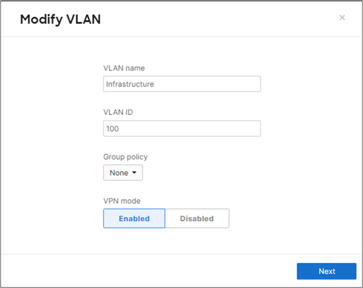
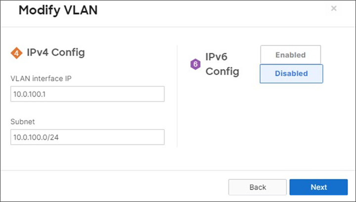
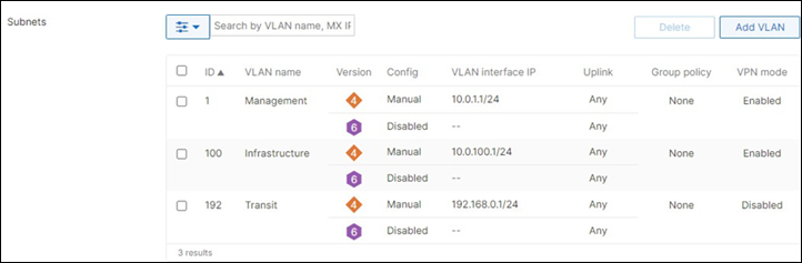
● As seen above, VLAN 1 needs to be kept at this stage to avoid losing connectivity to all downstream devices.
3. MX Addressing and VLANs: Navigate to Security and SD-WAN > Configure > DHCP, then under VLAN 100 AND 192 click on Fixed IP assignments and add entries for your network devices. (Tip: You can copy the MAC addresses from VLAN 1 and make sure to add the correct IP assignment to them). Then, click on Save at the bottom of the page.
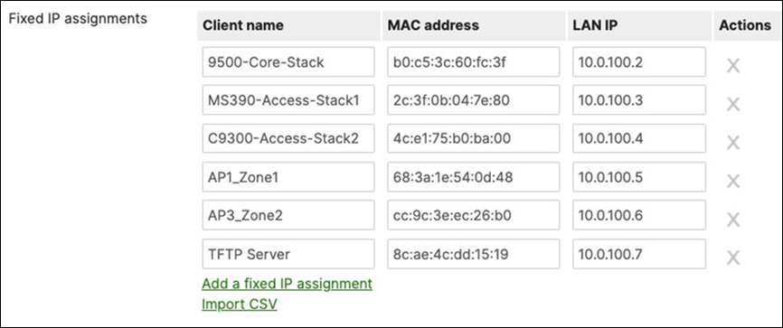
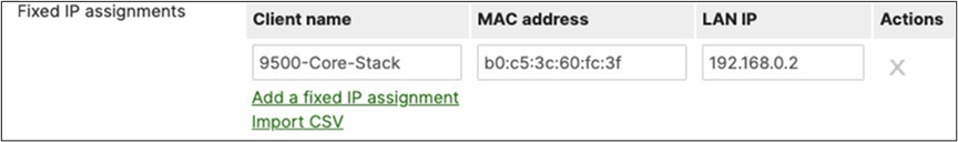
4. Create VLAN 100 and 192 on your C9500 Core Stack
| Switch>en Switch#conf t Enter configuration commands, one per line. End with CNTL/Z. 9500-02(config)#interface vlan 100 9500-02(config-if)#ip address dhcp 9500-02(config-if)#no shut 9500-02(config)#interface vlan 192 9500-02(config-if)#ip address dhcp 9500-02(config-if)#no shut 9500-02(config)#vlan 100 9500-02(config-if)#no shut 9500-02(config)#vlan 192 9500-02(config-if)#no shut 9500-02(config-if)#end 9500-02#wr mem Building configuration... [OK] |
5. Navigate to Switching > Configure > Switch ports and filter for MR (if you have tagged the ports accordingly, otherwise select your downlink ports manually), then change the Native VLAN on these switchports from Native VLAN 1 to Native VLAN 100. Also, please add VLAN 100 to the list of Allowed VLANs and remove VLAN 1 from the allowed list of VLANs. Then, click on Save at the bottom of the page.
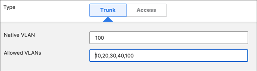
● Please note that this will cause disruption to client traffic
6. Navigate to Switching > Monitor > Switches and click on the first master switch then change the IP address settings from Static to DHCP and please leave the VLAN field blank. (DO NOT add VLAN 100 at this stage). Then, click on Save at the bottom of the window. Please repeat this for all master switches in your network.

● As seen from the above screen shot, the VLAN value has been kept empty at this stage
7. On your C9500 Core Stack, add an MST instance in VLAN 100 and VLAN 192
| 9500-01(config)#spanning-tree mst configuration 9500-01(config-mst)#instance 0 vlan 100 9500-01(config-mst)#instance 0 vlan 192 9500-01(config-mst)#name region1 9500-01(config-mst)#revision 1 9500-01(config-mst)#exit 9500-01(config)#spanning-tree mode mst 9500-01(config)#spanning-tree mst 0 priority 4096 9500-01(config)#exit 9500-01#wr mem Building configuration... [OK] 9500-01# |
8. Navigate to Switching > Monitor > Switch ports and filter for uplink (if you have tagged the ports accordingly, otherwise select your uplink ports manually), then change the Native VLAN on these switchports from Native VLAN 1 to Native VLAN 100. Also, please add VLAN 100 to the list of Allowed VLANs and remove VLAN 1 from the allowed list of VLANs. Then, click on Save at the bottom of the page.
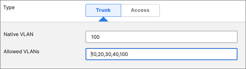
● Please note that this will cause the Access Stacks to go offline on the Meraki dashboard
9. On your C9500 Core Stack, change the Native VLAN on your downlink Port-channels to VLAN 100
| 9500-01(config)#interface po1 9500-01(config-if)#switchport trunk allowed vlan 10,20,30,40,100 9500-01(config-if)#switchport trunk native vlan 100 9500-01(config-if)#interface po2 9500-01(config-if)#switchport trunk allowed vlan 10,20,30,40,100 9500-01(config-if)#switchport trunk native vlan 100 9500-01(config)#end 9500-01#wr mem Building configuration... [OK] 9500-01# |
10. Shutdown all uplinks from C9500 Core Stack to Port 19 and 20 on your Secondary WAN Edge appliance to avoid having a dual-active situation.
| 9500-01(config)#interface twe1/0/24 9500-01(config-if)#shutdown 9500-01(config-if)#interface twe2/0/24 9500-01(config-if)#shutdown 9500-01(config)#end 9500-01# |
11. MX Addressing and VLANs: Navigate to Security and SD-WAN > Configure > Addressing and VLANs, then under Per-port settings, change the Native VLAN on your downlinks to VLAN 100 and allow both VLAN 100 and 192.
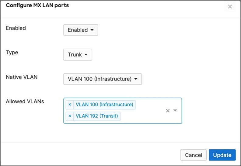
12. On your C9500 Core Stack, change the Native VLAN on your uplink to VLAN 100 and allow VLANs 100 and 192 (Please note that you will need to connect to your C9500 Core Stack via console access since VLAN 1 does not exist anymore on the upstream device which is the MX WAN Edge in this case):
| 9500-01(config)#define interface-range uplinks TwentyFiveGigE1/0/1-2 , TwentyFiveGigE2/0/1-2 9500-01(config)#interface range macro uplinks 9500-01(config-if)#switchport mode trunk 9500-01(config-if)#switchport trunk allowed vlan 100,192 9500-01(config-if)#switchport trunk native vlan 100 9500-01(config)#end 9500-01#wr mem Building configuration... [OK] 9500-01# |
13. On your C9500 Core Stack, create a default route for your SVI interfaces:
| 9500-01(config)#ip route 0.0.0.0 0.0.0.0 192.168.0.1 9500-01(config)#end 9500-01#wr mem Building configuration... [OK] 9500-01# |
14. Adjust your Static Routes on the MX to point to the transit VLAN instead of VLAN 1. Navigate to Security and SD-WAN > Configure > Addressing and VLANs and under Static routes click on a static route to change the next-hop. Please repeat that for all your static routes. Then, click on Save at the bottom of the page:
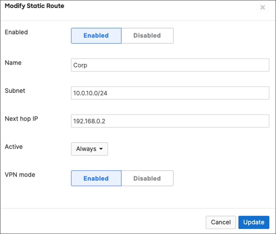

15. Wait for your Access Switches to come back online and acquire an IP address in the new Native VLAN 100. Then, proceed to the next step.
16. Now your switches should have acquired an IP address per the fixed IP assignment configuration. Navigate to Switching > Monitor > Switches then click on the first master switch and then change the IP address settings to static. Then, click on Save at the bottom of the window. Repeat this for all master switches in your network.

● Please repeat the above step for all stacks in your network
17. Navigate to your Primary WAN Edge device and ping 10.0.100.2 to make sure that it is reachable via VLAN 100. Then proceed to the next step.
18. Unshut the uplinks on your C9500 Core Stack to the Secondary WAN Edge appliance:
| 9500-01(config)#interface twe1/0/24 9500-01(config-if)#no shutdown 9500-01(config-if)#interface twe2/0/24 9500-01(config-if)#no shutdown 9500-01(config)#end 9500-01# |
19. Verify that all your devices have come back online and acquired an IP address in the new Management VLAN. Navigate to Organization > Monitor > Overview then click on the devices tab:
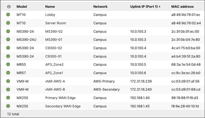
20. Navigate to Switching > Configure > Switch settings then change the Management VLAN configuration to VLAN 100. Then, click on Save at the bottom of the page.

21. Delete VLAN 1 from your MX appliance. Navigate to Security and SD-WAN > Configure > Addressing and VLANs and select the old Management VLAN 1 and then click on Delete. Then, click on Save at the bottom of the page.
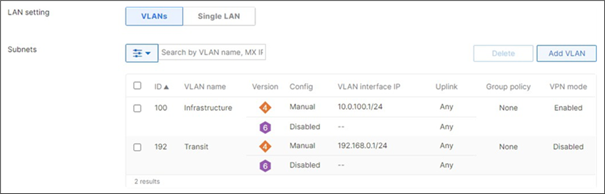
22. Where applicable - Please remember to adjust any routing between your Campus LAN and remote servers (e.g. Cisco ISE for 802.1x auth) as in this case devices will use the new Management VLAN 100 as the source of Radius requests. To verify that you have connectivity to your remote servers, Navigate to Wireless > Monitor > Access points then click on any AP and from the Tools section ping your remote server. Repeat this process from one of your switches.
![]()
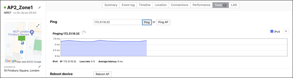
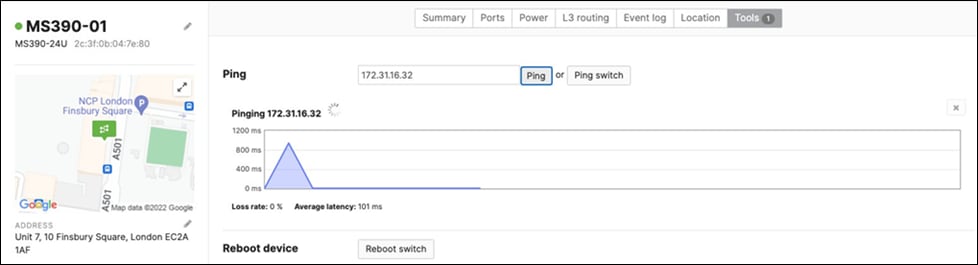
● With the current scope of the design, Cisco ISE resides in AWS and is reachable via AutoVPN which terminates on the vMX in AWS as well. As such, it was required to add a route on the VPC to 10.0.100.0/24 pointing to the vMX
● Also, please ensure that the new Management VLAN has been enabled with AutoVPN by navigating to Security and SD-WAN > Configure > Site-to-site VPN and ensure that VLAN 100 is enabled.
23. Where applicable - Please remember to adjust your Radius server configuration (e.g. Cisco ISE) as the Network devices now are grouped in a new Management VLAN 100. Please see the below example for Cisco ISE:
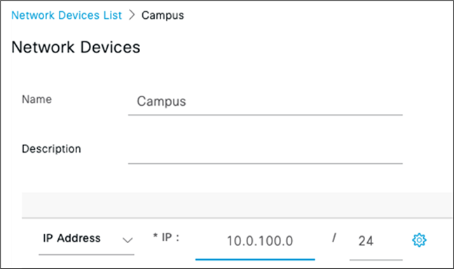
Overview
This option assumes that your OSPF domain is extended all the way to your core layer and thus there is no need to rely on STP between your Access and Core for convergence (as long as there are separate broadcast domains between Access and Core). It offers fast convergence since it relies on ECMP rather than STP layer 2 paths. However, it doesn't offer great flexibility in your VLAN design as each VLAN cannot span between multiple stacks/closets.
Pros:
● Deterministic route failover
● Fast convergence
● Relies on either stacking or gateway redundancy at upper layers
● Complete end to end separation between Management traffic and Client traffic
Cons:
● VLANs cannot span multiple stacks/closets
● Your backbone area size can be unmanageable
● Forces Layer 3 roaming across the Campus LAN
● Additional VLANs needed to route traffic between Campus LAN layers (aka Transit VLAN)
Logical Architecture
The following diagram shows the logical architecture for Layer 3 convergence within a campus LAN design leveraging Cloud Managed and Cloud Monitored Catalyst platform components:
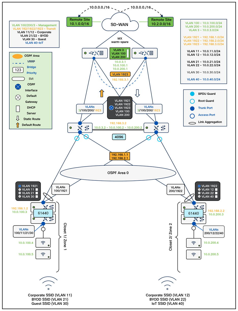
Physical Architecture
The following diagram shows the physical architecture and port list for this design:
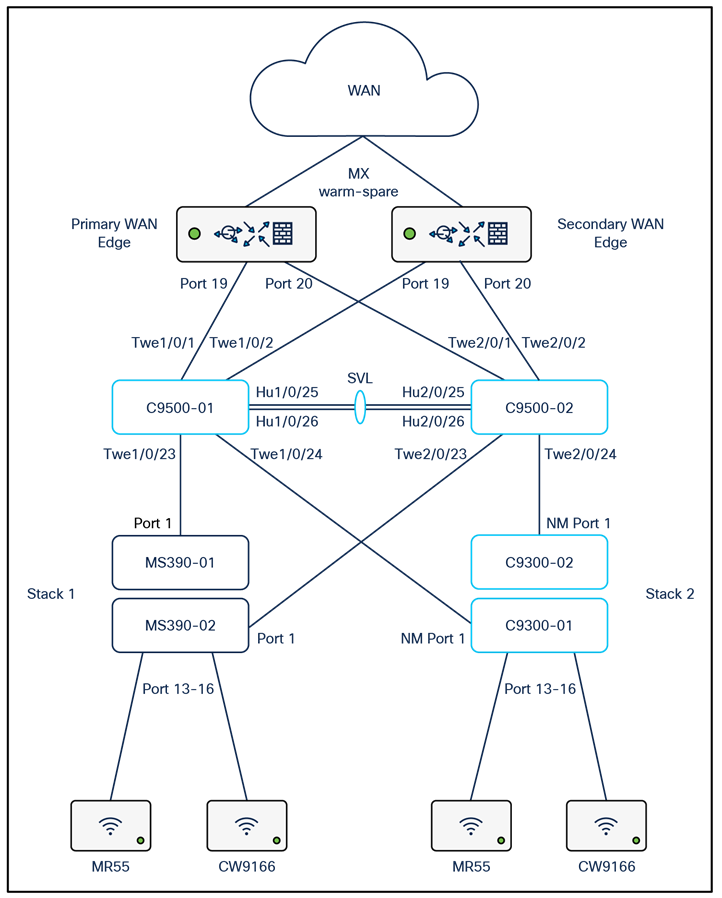
Assumptions
The following assumptions have been considered:
● It is assumed that Wireless roaming is required only within a specific Campus Zone
● It is assumed that VLANs are NOT spanning across multiple zones
● There will be NO use of VLAN 1 across the Campus LAN
● Corporate SSID (Broadcast in all zones) users are assigned VLAN 11/12 based on the AP zone.
● BYOD SSID (Broadcast in all zones) users are assigned VLAN 21/22 based on the AP zone.
● Guest SSID (Broadcast in Zone1) users are assigned VLAN 30 on all APs in that zone
● IoT SSID (Broadcast in zone2) users are assigned VLAN 40 on all APs in that Zone
● Access Switches will be running Layer 3 (SVIs and DHCP)
● MS390 Access Switches physically stacked together
● C9300-M Access Switches physically stacked together
● C9500 Core Switches with Stackwise-virtual stacking using SVLs
● Access Switch uplinks are in trunk mode with native VLAN = VLAN 1 (Management VLAN)
● STP root is at Distribution/Collapsed-core
● Network devices will be assigned fixed IPs from the management VLAN DHCP pool. Default Gateway will vary based on the Zone and stack.
Network Segments
Please check the following table for more information about the network segments (e.g. VLANs, SVIs, etc.) for this design:
| Network Segment |
VLAN ID |
Subnet |
Default Gateway |
Notes |
| Management (Core) |
3 |
10.0.3.0/24 |
10.0.3.1 |
SVI hosted on edge MX |
| Management (Stack1) |
100 |
10.0.100.0/24 |
10.0.100.1 |
SVI hosted on edge MX |
| Management (Stack2) |
200 |
10.0.200.0/24 |
10.0.200.1 |
SVI hosted on edge MX |
| Corporate Devices |
11 |
10.0.11.0/24 |
10.0.11.1 |
SVI hosted on Access switches (Zone 1) |
| 12 |
10.0.12.0/24 |
10.0.12.1 |
||
| BYOD Wireless Devices |
21 |
10.0.21.0/24 |
10.0.21.1 |
SVI hosted on Access switches (Zone 2) |
| 22 |
10.0.22.0/24 |
10.0.22.1 |
|
|
| Guest Wireless Devices |
30 |
10.0.30.0/24 |
10.0.30.1 |
SVI hosted on Access switches (Zone 1) |
| IoT Wireless Devices |
40 |
10.0.40.0/24 |
10.0.40.1 |
SVI hosted on Access switches (Zone 2) |
| Tech Tip: Please size your subnets based on your own requirements. The above table is for illustration purposes only. |
Quality of Service
| Application |
MR |
Access switches |
Core switches |
MX Appliance |
| SIP (Voice) |
EF DSCP 46 AC_Vo |
Trust incoming values DSCP 46 CoS 5 |
Trust incoming values |
EF DSCP 45 LLQ Unlimited |
| Webex and Skype |
AF41 DSCP 34 AC_VI |
Trust incoming values DSCP 34 CoS 4 |
Trust incoming values |
Af41 DSCP 34 High Priority |
| All Video and Music |
AF21 DSCP 18 AC_BE |
Trust incoming values DSCP 18 CoS 2 |
Trust incoming values |
AF21 DSCP 18 Medium Priority 5Mbps / Client |
| Software Updates |
AF11 DSCP 10 AC_BK |
Trust incoming values DSCP 10 CoS 1 |
Trust incoming values |
AF11 DSCP 10 Low Priority 10Mbps / Client |
Device List
| Device |
Name |
Management IP address |
Notes |
| MX250 MX250 |
Primary WAN Edge Spare WAN Edge |
10.0.3.1 |
warm-spare |
| C9500-24YCY C9500-24YCY |
C9500-01 C9500-02 |
10.0.3.2 |
Stackwise Virtual (C9500-Core-Stack) |
| MS390-24P MS390-24P |
MS390-01 MS390-02 |
10.0.100.2 |
Physical Stacking (Stack1-MS390) |
| C9300-24P C9300-24P |
C9300-01 C9300-02 |
10.0.200.2 |
Physical Stacking (Stack2-C9300) |
| MR55 |
AP1_Zone1 |
10.0.100.3 |
Tag = Zone1 |
| MR55 |
AP2_Zone1 |
10.0.100.4 |
Tag = Zone1 |
| C9166 (eq MR57) |
AP3_Zone2 |
10.0.200.3 |
Tag = Zone2 |
| C9166 (eq MR57) |
AP4_Zone2 |
10.0.200.4 |
Tag = Zone2 |
Access policies
| Access Policy Name |
Purpose |
Configuration |
Notes |
| Wired-1x |
802.1x Authentication via Cisco ISE for wired clients that support 802.1x |
Authentication method = my Radius server Radius CoA = enabled Host mode = Single-Host Access Policy type = 802.1x Suspend Port Bounce = Enabled Voice Clients = Bypass authentication Walled Garden = enabled |
Cisco ISE authentication and posture checks |
| Wired-MAB |
MAB Authentication via Cisco ISE for wired clients that do not support 802.1x |
Authentication method = my Radius server Radius CoA = disabled Host mode = Single-Host Access Policy type = MAC authentication bypass Suspect Port Bounce = Enabled Voice Clients = Bypass authentication Walled Garden = disabled |
Cisco ISE authentication |
Port List
| Device Name |
Port |
Far-end |
Port details |
Notes |
| WAN Edge |
|
|
|
|
| Primary WAN Edge |
19 |
9500-01 (port Twe1/0/1) |
Trunk (Native VLAN 3) |
Downlink, allowed VLANs 3, 100, 200, 1923 |
| 20 |
9500-02 (port Twe2/0/1) |
Trunk (Native VLAN 3) |
Downlink, allowed VLANs 3, 100, 200, 1923 |
|
| Spare WAN Edge |
19 |
9500-01 (port Twe1/0/2) |
Trunk (Native VLAN 3) |
Downlink, allowed VLANs 3, 100, 200, 1923 |
| 20 |
9500-02 (port Twe2/0/2) |
Trunk (Native VLAN 3) |
Downlink, allowed VLANs 3, 100, 200, 1923 |
|
| 9500-01 |
Twe1/0/1 |
Primary WAN Edge (Port 19) |
switchport mode trunk switchport trunk native vlan 3 switchport trunk allowed vlan 3,100,200,1923 auto qos trust dscp policy static sgt 2 trusted |
Uplink |
| Twe1/0/2 |
Spare WAN Edge (Port 19) |
switchport mode trunk switchport trunk native vlan 3 switchport trunk allowed vlan 3,100,200,1923 auto qos trust dscp policy static sgt 2 trusted |
Uplink |
|
| 9500-02 |
Twe2/0/1 |
Primary WAN Edge (Port 20) |
switchport mode trunk switchport trunk native vlan 3 switchport trunk allowed vlan 3,100,200,1923 auto qos trust dscp policy static sgt 2 trusted |
Uplink |
| Twe2/0/2 |
Spare WAN Edge (Port 20) |
switchport mode trunk switchport trunk native vlan 3 switchport trunk allowed vlan 3,100,200,1923 auto qos trust dscp policy static sgt 2 trusted |
Uplink |
|
| 9500-01 |
Twe1/0/23 |
MS390-01 (Port 1) |
switchport mode trunk switchport trunk native vlan 100 switchport trunk allowed vlan 100,1921 channel-group 1 mode active spanning-tree guard root auto qos trust dscp policy static sgt 2 trusted |
Downlink |
| Twe1/0/24 |
C9300-01 (Port 1) |
switchport mode trunk switchport trunk native vlan 200 switchport trunk allowed vlan 200,1922 channel-group 2 mode active spanning-tree guard root auto qos trust dscp policy static sgt 2 trusted |
Downlink |
|
| 9500-02 |
Twe2/0/23 |
MS390-02 (Port 1) |
switchport mode trunk switchport trunk native vlan 100 switchport trunk allowed vlan 100,1921 channel-group 1 mode active spanning-tree guard root auto qos trust dscp policy static sgt 2 trusted |
Downlink |
| Twe2/0/24 |
C9300-02 (Port 1) |
switchport mode trunk switchport trunk native vlan 200 switchport trunk allowed vlan 200,1922 channel-group 2 mode active spanning-tree guard root auto qos trust dscp policy static sgt 2 trusted |
Downlink |
|
| 9500-01 |
Hu1/0/25 |
C9500-02 (Port Hu2/0/26) |
stackwise-virtual link 1 |
Stackwise Virtual |
| Hu1/0/26 |
C9500-02 (Port Hu2/0/25) |
stackwise-virtual link 1 |
Stackwise Virtual |
|
| 9500-02 |
Hu2/0/25 |
C9500-01 (Port Hu1/0/26) |
stackwise-virtual link 1 |
Stackwise Virtual |
| Hu2/0/26 |
C9500-01 (Port Hu1/0/25) |
stackwise-virtual link 1 |
Stackwise Virtual |
|
| MS390-01 |
5-8 |
Wired Clients |
"Access (Data VLAN 11/12) Access Policy = Wired-1x PoE Enabled STP BPDU Guard Tag = Wired Clients 802.1x AdP: Corp" |
For wired clients supporting 802.1x |
| MS390-02 |
||||
| C9300-01 |
||||
| C9300-02 |
||||
| MS390-01 |
9-12 |
Wired Clients |
Access (Data VLAN 11/12) Access Policy = MAB PoE Enabled STP BPDU Guard Tag = Wired Clients MAB AdP: Corp |
For wired clients that do not support 802.1x |
| MS390-02 |
||||
| C9300-01 |
||||
| C9300-02 |
||||
| MS390-01 |
13-16 |
MR |
Trunk (Native VLAN 100/200) PoE Enabled STP BPDU Guard Tag = MR WLAN Peer SGT Capable AdP: Infrastructure |
Allowed VLANs: 11/12, 21/22, 30 or 40, 100/200 |
| MS390-01 |
1 |
9500-01 (port Twe1/0/23) |
Trunk (Native VLAN 100) PoE Disabled Name: Core 1 Tag = Uplink Peer SGT Capable AdP: Infrastructure |
Allowed VLANs: 100,1921 |
| MS390-02 |
1 |
9500-02 (Port Twe2/0/23) |
Trunk (Native VLAN 100) PoE Disabled Name: Core 2 Tag = Uplink Peer SGT Capable AdP: Infrastructure |
Allowed VLANs: 100,1921 |
| C9300-01 |
C9300-01 / C9300-NM-8X / 1 |
9500-01 (Port Twe1/0/24) |
Trunk (Native VLAN 200) PoE Disabled Name: Core 1 Tag = Uplink Peer SGT Capable AdP: Infrastructure |
Allowed VLANs: 200,1922 |
| C9300-02 |
C9300-02 / C9300-NM-8X / 1 |
9500-02 (Port Twe2/0/24) |
Trunk (Native VLAN 200) PoE Disabled Name: Core 2 Tag = Uplink Peer SGT Capable AdP: Infrastructure |
Allowed VLANs: 200,1922 |
Wireless SSID List
| SSID Name |
Broadcast |
Configuration |
Notes |
Firewall and Traffic Shaping |
| Acme Corp |
All APs |
Association = Enterprise with my Radius server Encryption = WPA2 only Splash Page = Cisco ISE Radius CoA = Enabled SSID mode = Bridge mode VLAN Tagging = 11/12 (based on AP tag) AdP Group = 10:Corp Radius override = Enabled Mandatory DHCP = Enabled Layer 2 isolation = Disabled Allow Clients access LAN = Allow Traffic Shaping = Enabled with default settings |
Cisco ISE Authentication and posture checks (172.31.16.32/1812) |
Layer 2 Isolation = Disabled Allow Access to LAN = Enabled Per-Client Bandwidth Limit = 50Mbps Per-SSID Bandwidth Limit = Unlimited Enable Default Traffic Shaping rules SIP - EF (DSCP 46) Software Updates - AF11 (DSCP 10) Webex and Skype - AF41 (DSCP 34) All Video and Music - AF21 (DSCP 18) |
| Acme BYOD |
All APs |
Association = Enterprise with my Radius server Encryption = WPA2 only 802.11w = Enabled Splash Page = Cisco ISE SSID mode = Bridge mode VLAN Tagging = 21/22 (based on AP tag) AdP Group = 20:BYOD Radius override = Disabled Mandatory DHCP = Enabled Layer 2 isolation = Disabled Allow Clients access LAN = Allow Traffic Shaping = Enabled with default settings |
Cisco ISE Authentication (via Azure AD) and posture checks. Dynamic GP assignment (Radius attribute = Airospace-ACLNAME) |
Layer 2 Isolation = Disabled Allow Access to LAN = Enabled Per-Client Bandwidth Limit = 50Mbps Per-SSID Bandwidth Limit = Unlimited Enable Default Traffic Shaping rules SIP - EF (DSCP 46) Software Updates - AF11 (DSCP 10) Webex and Skype - AF41 (DSCP 34) All Video and Music - AF21 (DSCP 18) |
| Guest |
Zone1 |
Association = Enterprise with my Radius server Encryption = WPA1 and WPA2 802.11w = Enabled Splash Page = Click Through SSID mode = Bridge mode VLAN Tagging = 30 AdP Group = 30:Guest Radius override = Disabled Mandatory DHCP = Enabled Layer 2 isolation = Enabled Allow Clients access LAN = Deny Per SSID limit = 100Mbps Traffic Shaping = Enabled with default settings |
Meraki Authentication |
Allow Access to LAN = Disabled Per-Client Bandwidth Limit = 5Mbps Per-SSID Bandwidth Limit = 100Mbps Enable Default Traffic Shaping rules SIP - EF (DSCP 46) Software Updates - AF11 (DSCP 10) Webex and Skype - AF41 (DSCP 34) All Video and Music - AF21 (DSCP 18) |
| Acme IoT |
Zone2 |
Association = identity PSK with Radius Encryption = WPA1 and WPA2 802.11r = Disabled 802.11w = Disabled Splash Page = None Radius CoA = Disabled SSID mode = Bridge mode VLAN Tagging = 40 AdP Group = 40:IoT Radius override = Disabled Mandatory DHCP = Enabled Allow Clients access LAN = Deny Per SSID limit = 10Mbps Traffic Shaping = Enabled with default settings |
Cisco ISE is queried at association time to obtain a passphrase for a device based on its MAC address. Dynamic GP assignment (Radius attribute Filter-Id) |
Layer 2 Isolation = Disabled Allow Access to LAN = Enabled Per-Client Bandwidth Limit = 5Mbps Per-SSID Bandwidth Limit = Unlimited Enable Default Traffic Shaping rules SIP - EF (DSCP 46) Software Updates - AF11 (DSCP 10) Webex and Skype - AF41 (DSCP 34) All Video and Music - AF21 (DSCP 18) |
| Tech Tip: ● The above configuration is for illustration purposes only. Please configure your SSIDs based on your own requirements (mode, IP assignment, etc.). ● Please note that Adaptive Policy on MR requires MR-ADV license. For more information about the requirements, please refer to this document. |
Configuration and Implementation Guidelines
It is assumed that by this stage, Catalyst devices have been added to dashboard for either Monitoring (e.g. C9500) and/or Management (e.g. C9300). For more information, please refer to the above section.
Before proceeding, please make sure that you have the appropriate licenses claimed into your dashboard account.
1. Login to your dashboard account (or create an account if you don't have one)
2. Navigate to Organization > Configure > Inventory
3. For Co-term license model, click on Claim. And for PDL, please click on Add
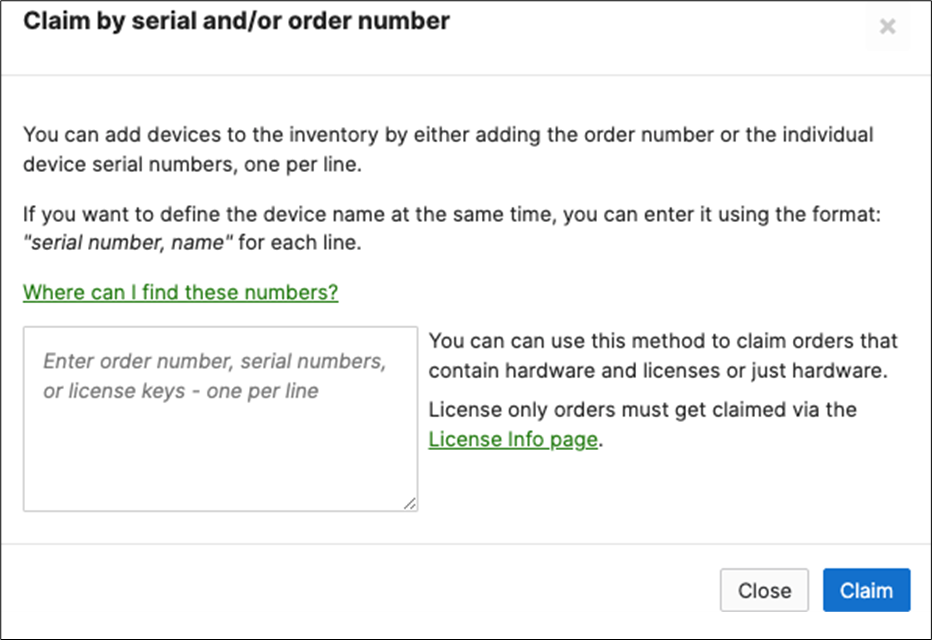
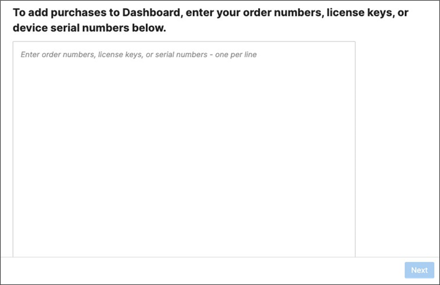
4. Enter the order and/or serial number(s) to claim the devices into your account. For PDL, click Next then please choose to add them to Inventory (Do not add them to a network)
5. Create a Dashboard Network: Navigate to Organization > Configure > Create network to create a network for your Campus LAN (Or use an existing network if you already have one). If you are creating a new network, please choose "Combined" as this will facilitate a single topology diagram for your Campus LAN. Choose a name (e.g. Campus) and then click Create network
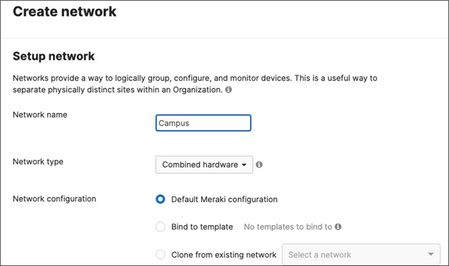
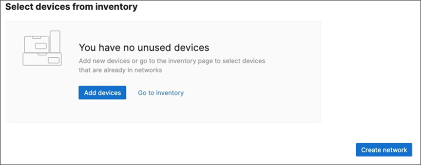
6. Dashboard Network Settings: Navigate to Network-wide > Configure > General and choose the settings for your network (e.g. Time zone, Traffic Analytics, firmware upgrade day/time, etc.)
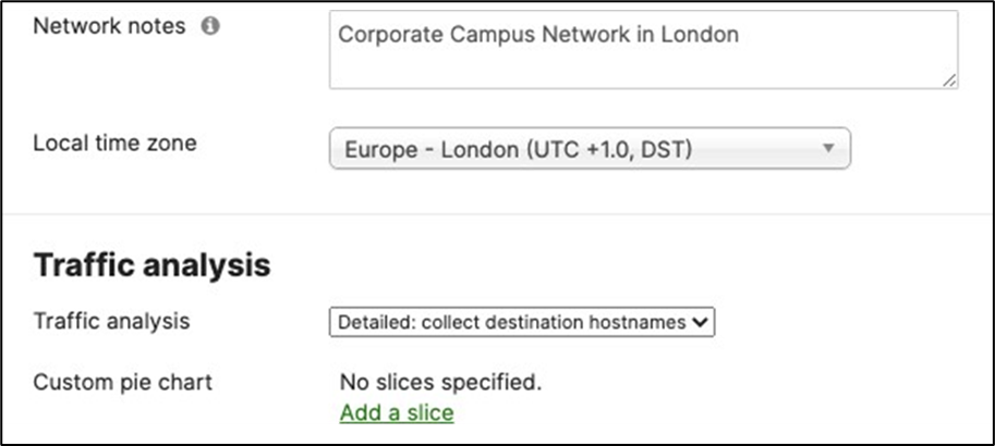
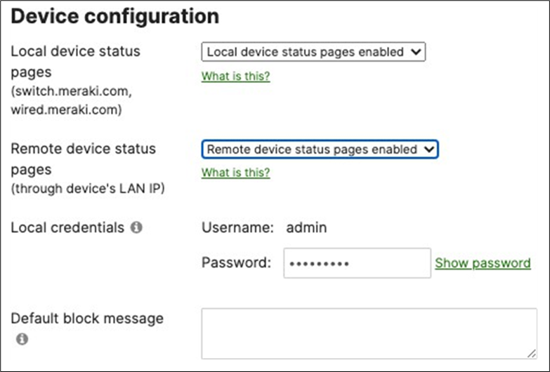
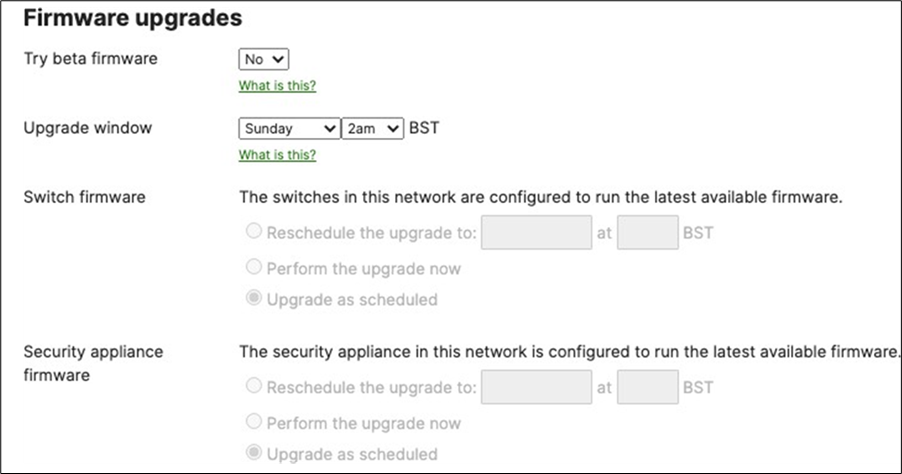
7. Schedule Firmware Upgrade: Navigate to Organization > Configure > Firmware upgrades to select the firmware for your devices such that devices upgrade once they connect to dashboard. Select the device type then click on Schedule upgrade.
8. Add Devices to a Dashboard Network: Navigate to Organization > Configure > Inventory.
● For Co-term licensing model, select the MS390 and C9300 switches and the Primary WAN Edge then click on Add then choose the Network Campus
● For PDL licensing model, select the MS390 and C9300 switches and the Primary WAN Edge then click on Change network assignment and then choose the Network Campus
● Please DO NOT add the Secondary WAN Edge device at this stage
9. Rename MX Security Appliance: Navigate to Security and SD-WAN > Monitor > Appliance status then click on the edit button to rename the MX to Primary WAN Edge then click on Save.
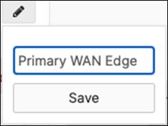
10. MX Connectivity: Plug in your WAN uplink(s) on the Primary WAN Edge MX then power it on and wait for it to come online on dashboard. This might take a few minutes as the MX will download its firmware and configuration. Navigate to Security and SD-WAN > Configure > Appliance status and verify that the MX has come online and that its firmware and configuration is up to date.
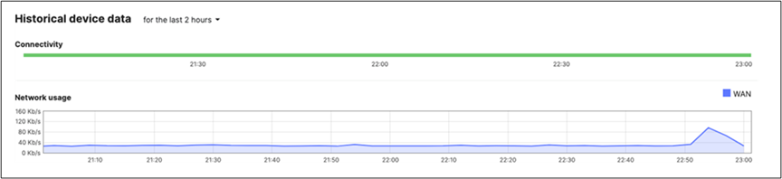
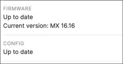
11. Rename Access Switches: Navigate to Switching > Monitor > Switches then click on each MS390 and C9300 switch and then click on the edit button on top of the page to rename it per the above table then click on Save such that all your switches have their designated names.
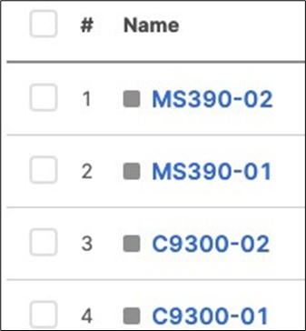
12. Rename MR APs: Navigate to Wireless > Monitor > Access points then click on each AP and then click on the edit button on top of the page to rename it per the above table then click on Save such that all your APs have their designated names.
13. MR AP Tags: Navigate to Wireless > Monitor > Access points then click on each AP and then click on the edit button next to TAGS to add Tags to your AP per the above table then click on Save such that all your APs have their designated tags.
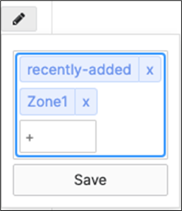
14. MX Addressing and VLANs: Navigate to Security and SD-WAN > Configure > Addressing and VLANs, and in the Deployment Settings menu select Routed mode. Further down the page on the Routing menu, click on VLANs then click on Add VLAN to add your Management and Transit VLANs then click on Create. Then for the per-port VLAN settings, select your downlink ports (19 and 20) and click on Edit and configure them as Trunk with VLAN 3 (Allowed VLANs 3, 100, 200, 1923) and click on Update. Finally, click on Save at the bottom of the page.
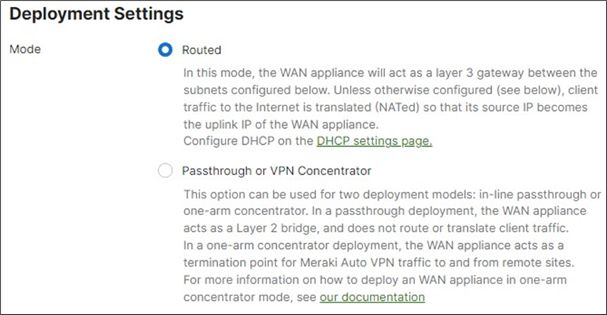
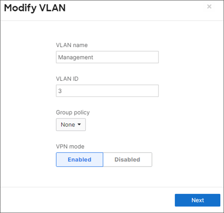
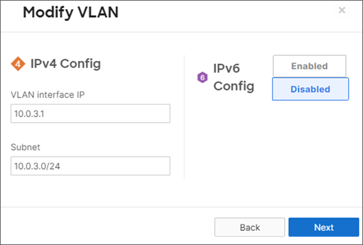
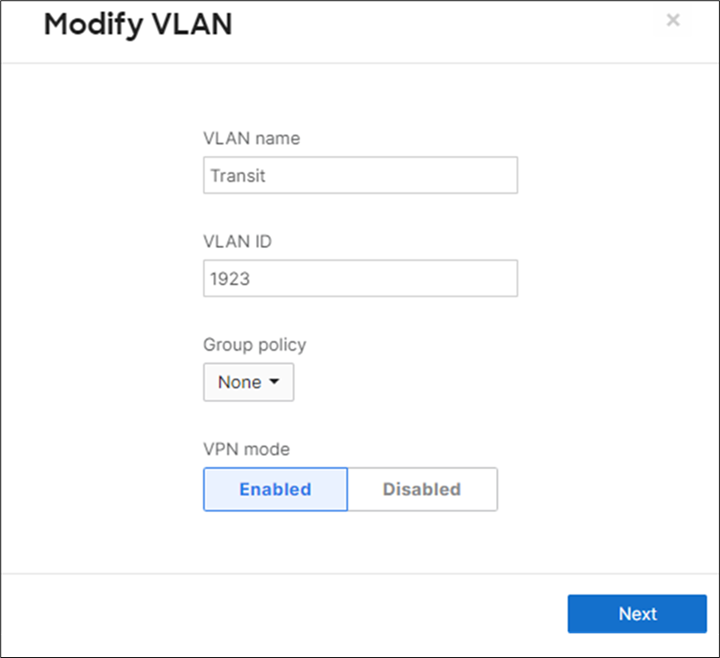
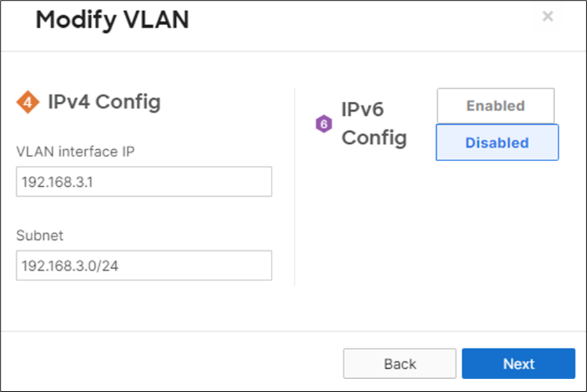
● Please repeat the above steps to create VLANs 100 and 200
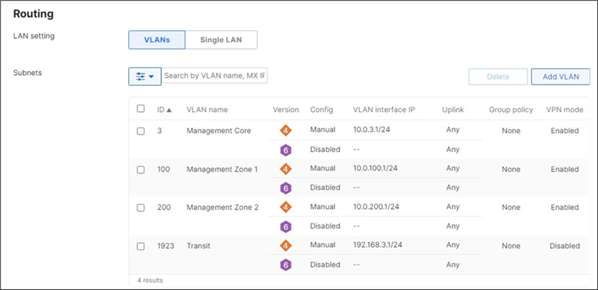
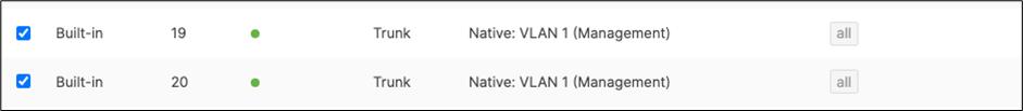
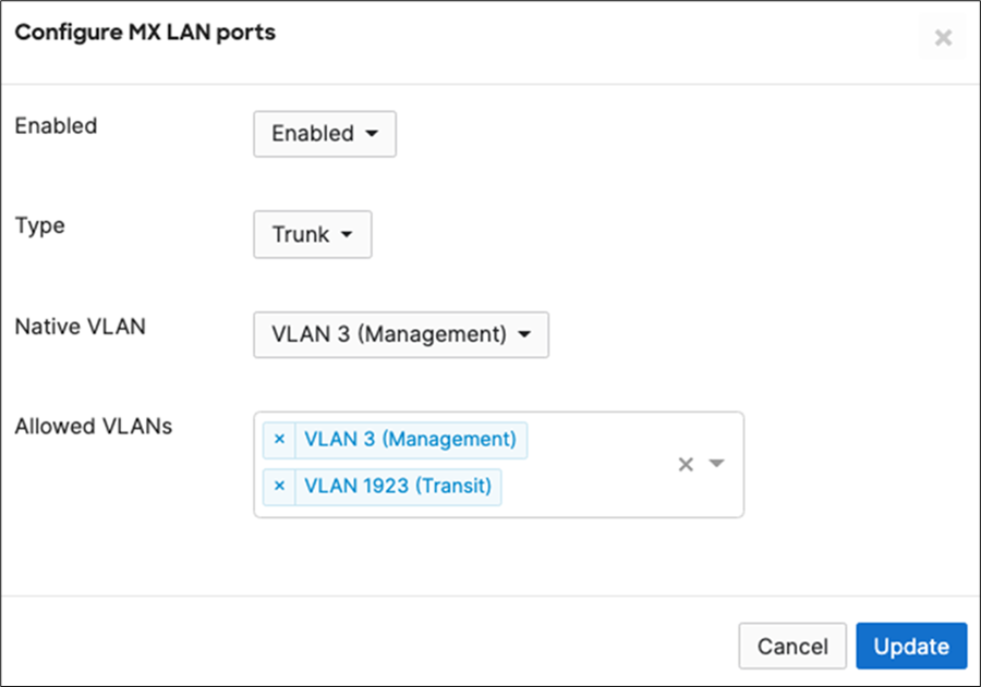
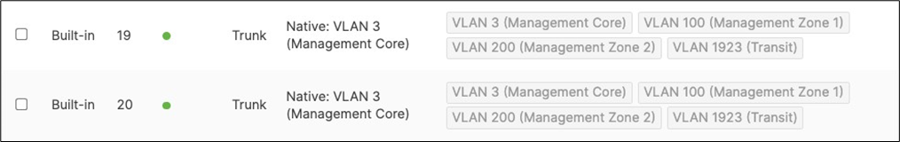
15. Campus LAN Static Routes: Create Static Routes for your Campus network by navigating further down the page to Static routes then click on Add Static Route. Start by adding your Corporate LAN subnet then click on Update and then add static routes to all other subnets (e.g. BYOD, Guest and IoT). Finally, click on Save at the bottom of the page. (The Next hop IP that you have used here will be used to create a fixed assignment for the Core Stack later in DHCP settings).

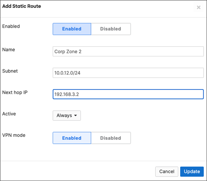
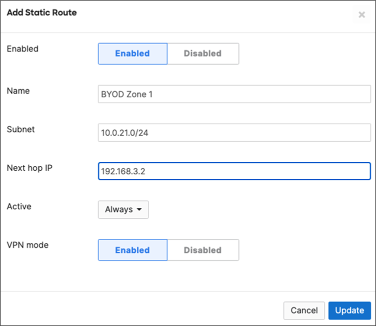
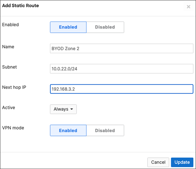
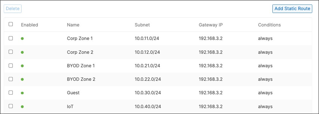
16. Optional - If you are accessing any resources over Meraki SD-WAN, please navigate to Security and SD-WAN > Configure > Site-to-site VPN and enable VPN based on your topology and traffic flow requirements. (In this case, we will configure this Campus as Spoke with Split Tunneling)
● Choose Type: Spoke then click on Add a hub and select your hub site where you need access to resources via VPN. You can also add multiple hubs for resiliency. To choose Split Tunneling, please leave the box next to the Hub unticked as shown below.
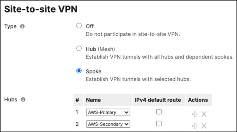
● Under VPN Settings, choose which subnet to be Enabled in VPN (e.g. Management VLAN will be required for Radius authentication purposes as the MR/MS390/C9300 devices will reach out to Cisco ISE using their management IP). Any Subnet that needs to access resources via VPN must be Enabled otherwise keep it as Disabled.
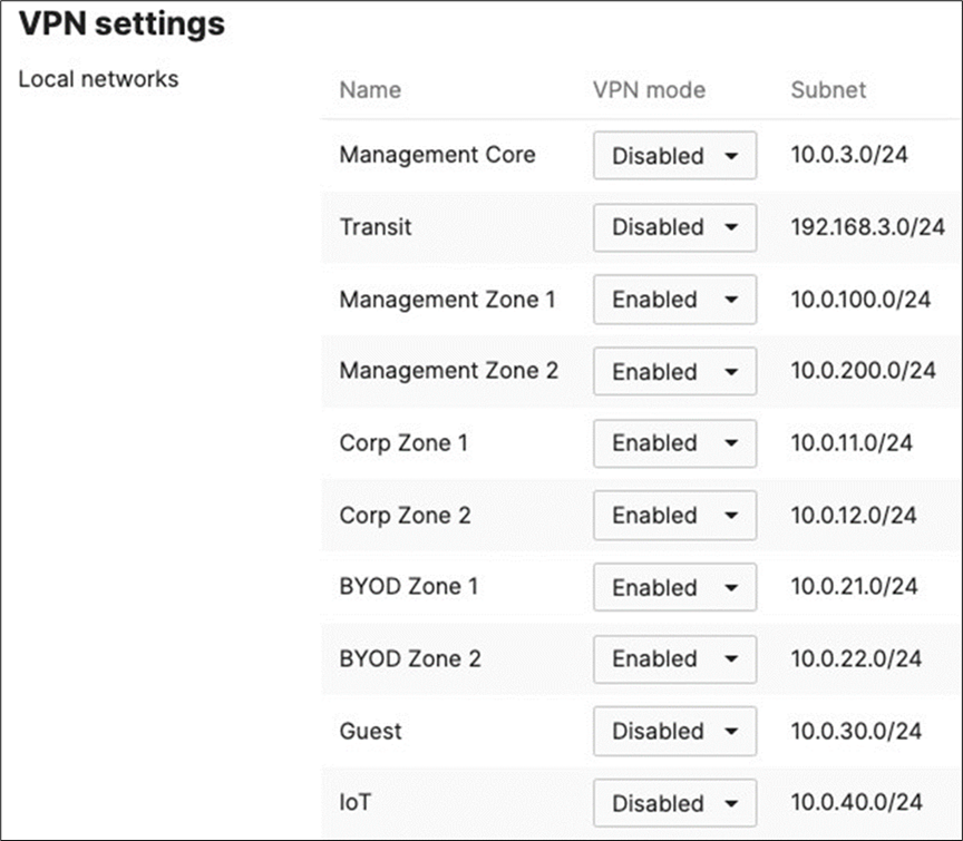
● Finally, click on Save at the bottom of the page on the Hub site, please make sure to advertise the subnets that are required to be reachable via VPN. Navigate to Security and SD-WAN > Configure > Site-to-site VPN then add a local network then click Save at the bottom of the page (Please make sure that you are configuring this on the Hub's dashboard network).
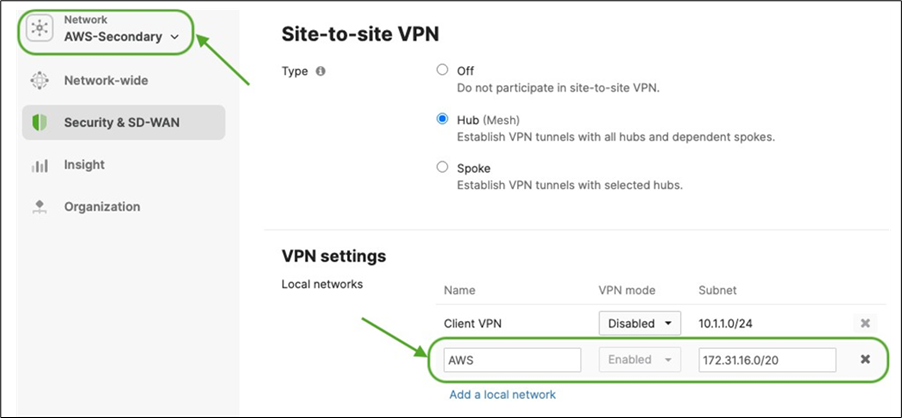
17. Optional - Verify that your VPN has come up by selecting your Campus LAN dashboard network from the Top-Left Network drop-down list and then navigate to Security and SD-WAN > Monitor > VPN status then check the status of your VPN peers. Next, navigate to Security and SD-WAN > Monitor > Route table and check the status of your remote subnets that are reachable via VPN. You can also verify connectivity by pinging a remote subnet (e.g. 172.31.16.32 which is Cisco ISE) by navigating to Security and SD-WAN > Monitor > Appliance status then click on Tools and ping the specified IP address (Please note that the MX will choose the highest VLANs interface IP participating in VPN by default as the source).
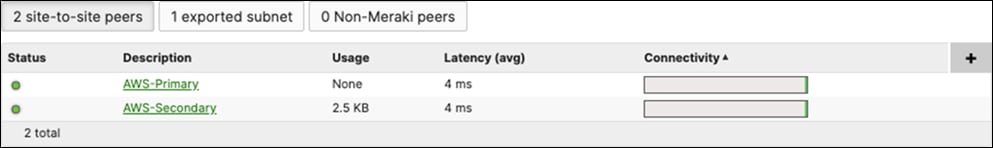
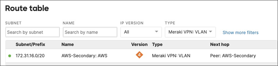
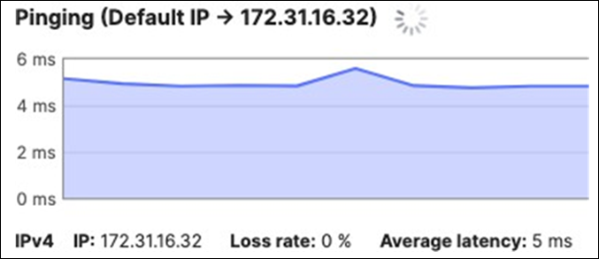
Please note that in order to ping a remote subnet, you must either have BGP enabled or have static routes at the far-end pointing back to the Campus LAN local subnets. (In other words, the source of your traffic which for ping by default is the highest VLAN participating in AutoVPN if not otherwise specified).
In this example, the VPC in AWS has been configured with a Route Entry to route 10.0.100.0/24 and 10.0.200.0/24 via the vMX deployed in AWS that has a VPN tunnel back to the Campus LAN site.

If the remote VPN peer (e.g. AWS) is configured in Routed mode, the static route is not required since traffic will always be NAT'd to a local reachable IP address. Please also don't forget to create Network Device groups on Cisco ISE for your network devices to be able to send authentication messages to Cisco ISE. See the below example:
18. SD-WAN and Traffic Shaping Configuration: To configure Traffic Shaping settings for your Campus LAN site. Navigate to Security and SD-WAN > Configure > SD-WAN and Traffic Shaping to configure your preferred settings. For the purpose of this CVD, the default traffic shaping rules will be used to mark traffic with a DSCP tag without policing egress traffic (except for traffic marked with DSCP 46) or applying any traffic limits. (Please adjust these settings based on your requirements such as traffic limits or priority queue values. For more information about traffic shaping settings on the MX devices, please refer to the following article).

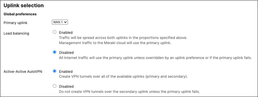
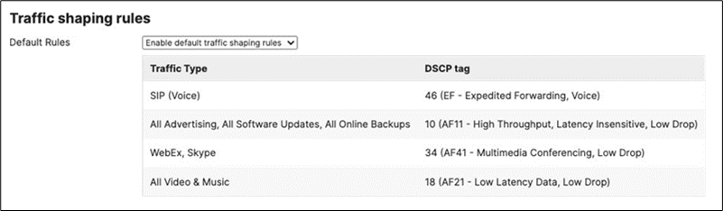
19. Optional - Configure Threat Protection (Requires Advanced License or above) for your Campus LAN site. Navigate to Security and SD-WAN > Configure > Threat Protection and choose the settings that meet your site requirements. Please see the following configuration example:

20. Click on Save at the bottom of the page.
21. Optional - Configure Content Filtering Settings (Requires Advanced License or above) for your Campus LAN site. Navigate to Security and SD-WAN > Configure > Content filtering and choose the settings that meet your site requirements. Please see the following configuration example:

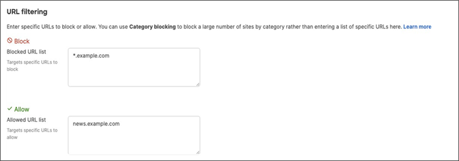
22. Click on Save at the bottom of the page.
23. Core Switch Uplinks: On the Catalyst 9500 core switches, Connect their uplinks to the Primary WAN Edge MX and power them both on.
24. Core Switch Network Access: Connect to the first C9500 switch via console and configure it with the following commands:
| Switch>en Switch#conf t Enter configuration commands, one per line. End with CNTL/Z. Switch(config)#hostname 9500-01 9500-01(config)#ip domain name meraki-cvd.local 9500-01(config)#cdp run 9500-01(config)#lldp run 9500-01(config)#stackwise Please reload the switch for Stackwise Virtual configuration to take effect Upon reboot, the config will be part of running config but not part of start-up config. 9500-01(config-stackwise-virtual)#domain 1 9500-01(config)#exit 9500-01(config)#interface Twe1/0/1 9500-01(config-if)#switchport mode trunk 9500-01(config-if)#switchport trunk native vlan 3 9500-01(config-if)#switchport trunk allowed vlan 3,100,200,1923 9500-01(config-if)#no shut 9500-01(config-if)#exit 9500-01(config)#interface Twe1/0/2 9500-01(config-if)#switchport mode trunkk 9500-01(config-if)#switchport trunk native vlan 3 9500-01(config-if)#switchport trunk allowed vlan 3,100,200,1923 9500-01(config-if)#no shut 9500-01(config-if)#exit 9500-01(config)#interface vlan 3 9500-01(config-if)#ip address dhcp 9500-01(config-if)#no shut 9500-01(config-if)#exit 9500-01(config)#interface vlan 100 9500-01(config-if)#ip address dhcp 9500-01(config-if)#no shut 9500-01(config-if)#exit 9500-01(config)#interface vlan 200 9500-01(config-if)#ip address dhcp 9500-01(config-if)#no shut 9500-01(config-if)#exit 9500-01(config)#interface vlan 1923 9500-01(config-if)#ip address 192.168.3.2 255.255.255.0 9500-01(config-if)#no shut 9500-01(config-if)#end 9500-01# 9500-01#sh ip int brief Interface IP-Address OK? Method Status Protocol Vlan3 10.0.3.2 YES DHCP up up Vlan100 10.0.100.2 YES DHCP up up Vlan200 10.0.200.2 YES DHCP up up Vlan1923 192.168.3.2 YES manual up up GigabitEthernet0/0 unassigned YES NVRAM down down TwentyFiveGigE1/0/1 unassigned YES unset up up TwentyFiveGigE1/0/2 unassigned YES unset up up 9500-01#ping 8.8.8.8 Type escape sequence to abort. Sending 5, 100-byte ICMP Echos to 8.8.8.8, timeout is 2 seconds: !!!!! Success rate is 100 percent (5/5), round-trip min/avg/max = 4/4/5 ms 9500-01#ping cisco.com Type escape sequence to abort. Sending 5, 100-byte ICMP Echos to 72.163.4.185, timeout is 2 seconds: !!!!! Success rate is 100 percent (5/5), round-trip min/avg/max = 109/109/109 ms 9500-01#switch 1 renumber 1 9500-01#switch priority 5 9500-01#wr mem Building configuration... [OK] |
25. Core Switch Network Access: Connect to the second C9500 switch via console and configure it with the following commands:
| Switch>en Switch#conf t Enter configuration commands, one per line. End with CNTL/Z. Switch(config)#hostname 9500-02 9500-02(config)#ip domain name meraki-cvd.local 9500-01(config)#cdp run 9500-01(config)#lldp run 9500-02(config)#stackwise Please reload the switch for Stackwise Virtual configuration to take effect Upon reboot, the config will be part of running config but not part of start-up config. 9500-02(config-stackwise-virtual)#domain 1 9500-02(config)#exit 9500-02(config)#interface Twe1/0/1 9500-01(config-if)#switchport mode trunk 9500-02(config-if)#switchport trnk native vlan 3 9500-01(config-if)#switchport trunk allowed vlan 3,100,200,1923 9500-02(config-if)#no shut 9500-02(config-if)#exit 9500-02(config)#interface Twe1/0/2 9500-01(config-if)#switchport mode access 9500-02(config-if)#switchport access vlan 3 9500-01(config-if)#switchport trunk allowed vlan 3,100,200,1923 9500-02(config-if)#no shut 9500-02(config-if)#exit 9500-02(config)#interface vlan 3 9500-02(config-if)#ip address dhcp 9500-02(config-if)#no shut 9500-01(config)#interface vlan 100 9500-01(config-if)#ip address dhcp 9500-01(config-if)#no shut 9500-01(config-if)#exit 9500-01(config)#interface vlan 200 9500-01(config-if)#ip address dhcp 9500-01(config-if)#no shut 9500-01(config-if)#exit 9500-01(config)#interface vlan 1923 9500-01(config-if)#no shut 9500-01(config-if)#end 9500-01# 9500-01#sh ip int brief Interface IP-Address OK? Method Status Protocol Vlan3 10.0.3.3 YES DHCP up up Vlan100 10.0.100.3 YES DHCP up up Vlan200 10.0.200.3 YES DHCP up up Vlan1923 unassigned YES manual up down GigabitEthernet0/0 unassigned YES NVRAM down down TwentyFiveGigE1/0/1 unassigned YES unset up up TwentyFiveGigE1/0/2 unassigned YES unset up up 9500-02#ping 8.8.8.8 Type escape sequence to abort. Sending 5, 100-byte ICMP Echos to 8.8.8.8, timeout is 2 seconds: !!!!! Success rate is 100 percent (5/5), round-trip min/avg/max = 4/4/5 ms 9500-02#ping cisco.com Type escape sequence to abort. Sending 5, 100-byte ICMP Echos to 72.163.4.185, timeout is 2 seconds: !!!!! Success rate is 100 percent (5/5), round-trip min/avg/max = 109/109/109 ms 9500-02#switch 1 renumber 2 9500-02#switch priority 1 9500-02#wr mem Building configuration... [OK] |
26. SVL Configuration: Now that both C9500 switches have access to the network, proceed to configure the Stackwise Virtual Links per the port list provided above (In this case using two ports for the SVL providing a total stacking bandwidth of 80 Gbps).
| 9500-01(config)#interface HundredGigE1/0/25 9500-01(config-if)#stackwise-virtual link 1 9500-01(config-if)#no shut 9500-01(config-if)#exit 9500-01(config)#interface HundredGigE1/0/26 9500-01(config-if)#stackwise-virtual link 1 9500-01(config-if)#no shut 9500-01(config-if)#end 9500-01#wr mem Building configuration... [OK] 9500-01#reload Proceed with reload? [confirm] |
| 9500-02(config)#interface HundredGigE1/0/25 9500-02(config-if)#stackwise-virtual link 1 9500-02(config-if)#no shut 9500-02(config-if)#exit 9500-02(config)#interface HundredGigE1/0/26 9500-02(config-if)#stackwise-virtual link 1 9500-02(config-if)#no shut 9500-02(config-if)#end 9500-02#wr mem Building configuration... [OK] 9500-02#reload Proceed with reload? [confirm] |
27. Connect Stacking Cables: Whilst the C9500 switches are reloading, connect the stacking cables on both switches.
28. Verify Stackwise Configuration: Please wait for about 10 minutes for the switches to come back up and initialize the stack. Then, connect to the 9500-01 (Stack Master) via console to verify that the stack is operational. The stackwise-virtual link should be U (Up) and R (Ready).
| 9500-01#show stackwise-virtual Stackwise Virtual Configuration: ---------------------------- Stackwise Virtual : Enabled Domain Number : 1
Switch Stackwise Virtual Link Ports ----------------------------- 1 HundredGigE1/0/25 HundredGigE1/0/26 2 HundredGigE2/0/25 HundredGigE2/0/26 9500-01# 9500-01#show stackwise-virtual link Stackwise Virtual Link(SVL) Information: ----------------------------- Flags: ----- Link Status ----------- U-Up D-Down Protocol Status ----------- S-Suspended P-Pending E-Error T-Timeout R-Ready ----------------------------- Switch SVL Ports Link-Status Protocol-Status --------------------------------------- 1 1 HundredGigE1/0/25 U R HundredGigE1/0/26 U R 2 1 HundredGigE2/0/25 U R HundredGigE2/0/26 U R
9500-01# 9500-01#show stackwise-virtual bandwidth Switch Bandwidth ---------------- 1 80G 2 80G
9500-01# 9500-01#sh switch Switch/Stack Mac Address : b0c5.3c60.fba0 - Local Mac Address Mac persistency wait time: Indefinite H/W Current Switch# Role Mac Address Priority Version State *1 Active b0c5.3c60.fba0 5 V02 Ready 2 Standby 40b5.c111.01e0 1 V02 Ready
9500-01# |
29. Optional - Attach and configure stackwise-virtual dual-active-detection: DAD is a feature used to avoid a dual- active situation within a stack of switches. It will rely on a direct attachment link between the two switches to send hello packets and determine if the active switch is responding or not. Please note that DAD cannot be applied to any SVL links and has to be a dedicated interface. For the purpose of this CVD, interface HundredGigE1/0/27 and HundredGigE2/0/27 will be used for enabling DAD between the two C9500 switches.
| 9500-01#configure terminal 9500-01(config)#interface HundredGigE1/0/27 9500-01(config-if)#stackwise-virtual dual-active-detection WARNING: All the extraneous configurations will be removed for HundredGigE1/0/27 on reboot. INFO: Upon reboot, the config will be part of running config but not part of start-up config. 9500-01(config-if)#interface HundredGigE2/0/27 9500-01(config-if)#stackwise-virtual dual-active-detection WARNING: All the extraneous configurations will be removed for HundredGigE1/0/27 on reboot. INFO: Upon reboot, the config will be part of running config but not part of start-up config. 9500-01(config-if)#end 9500-01#wr mem Building configuration... [OK] 9500-01#reload Reload command is being issued on Active unit, this will reload the whole stack Proceed with reload? [confirm]Connection to 10.0.3.2 closed by remote host. Connection to 10.0.3.2 closed. >> 9500-01#sh stackwise-virtual dual-active-detection In dual-active recovery mode: No Recovery Reload: Enabled Dual-Active-Detection Configuration: ----------------------------------- Switch Dad port Status ---------------------------- 1 HundredGigE1/0/27 up 2 HundredGigE2/0/27 up
9500-01# |
30. Configure Multiple Spanning Tree Protocol (802.1s). Connect to the 9500-01 (Stack Master) via console and use the following commands:
| 9500-01(config)#spanning-tree mst configuration 9500-01(config-mst)#instance 0 vlan 3,100,200,1921,1922,1923 9500-01(config-mst)#name region1 9500-01(config-mst)#revision 1 9500-01(config-mst)#exit 9500-01(config)#spanning-tree mode mst 9500-01(config)#spanning-tree mst 0 priority 4096 9500-01(config)#exit 9500-01#wr mem Building configuration... [OK] 9500-01# |
31. Verify Spanning Tree Configuration (Please note that interface Twe2/0/1 will be in STP blocking state due to the fact that both uplinks are connected to the same MX edge device at this stage).
| 9500-01#show spanning-tree MST0 Spanning tree enabled protocol mstp Root ID Priority 4096 Address b0c5.3c60.fba0 This bridge is the root Hello Time 2 sec Max Age 20 sec Forward Delay 15 sec Bridge ID Priority 4096 (priority 4096 sys-id-ext 0) Address b0c5.3c60.fba0 Hello Time 2 sec Max Age 20 sec Forward Delay 15 sec Interface Role Sts Cost Prio.Nbr Type Twe1/0/1 Desg FWD 2000 128.193 P2p Twe2/0/1 Back BLK 2000 128.385 P2p
9500-01# |
32. Configure STP Root Guard and UDLD on the Core Stack Downlinks:
| 9500-01#configure terminal Enter configuration commands, one per line. End with CNTL/Z. 9500-01(config)#int Twe1/0/23 9500-01(config-if)#spanning-tree guard root 9500-01(config-if)#udld port aggressive 9500-01(config-if)#int Twe1/0/24 9500-01(config-if)#spanning-tree guard root 9500-01(config-if)#udld port aggressive 9500-01(config-if)#int Twe2/0/23 9500-01(config-if)#spanning-tree guard root 9500-01(config-if)#udld port aggressive 9500-01(config-if)#int Twe2/0/24 9500-01(config-if)#spanning-tree guard root 9500-01(config-if)#udld port aggressive 9500-01(config-if)#end 9500-01#wr mem Building configuration... [OK] 9500-01# |
33. Optional - STP Hygiene: It is recommended to configure STP Root Guard on all C9500 Core Stack downlinks to avoid any new introduced downstream switches from claiming root bridge status.
| 9500-01#configure terminal Enter configuration commands, one per line. End with CNTL/Z. 9500-01(config)#define interface-range stp-protect TwentyFiveGigE1/0/3 - 22 9500-01(config)#interface range macro stp-protect 9500-01(config-if-range)#spanning-tree guard root 9500-01(config-if-range)#exit 9500-01(config)#define interface-range stp-protect2 TwentyFiveGigE2/0/3 - 22 9500-01(config)#interface range macro stp-protect2 9500-01(config-if-range)#spanning-tree guard root 9500-01(config-if)#end 9500-01#wr mem Building configuration... [OK] 9500-01# |
34. Optional - STP Hygiene: It is recommended to configure STP Loop Guard on all C9500 Core Stack un-used stacking links.
| 9500-01#configure terminal Enter configuration commands, one per line. End with CNTL/Z. 9500-01(config)#interface HundredGigE1/0/27 9500-01(config-if)#spanning-tree guard loop 9500-01(config-if-range)#exit 9500-01(config)#interface HundredGigE1/0/28 9500-01(config-if)#spanning-tree guard loop 9500-01(config-if)#exit 9500-01(config)#interface HundredGigE2/0/27 9500-01(config-if)#spanning-tree guard loop 9500-01(config-if-range)#exit 9500-01(config)#interface HundredGigE2/0/28 9500-01(config-if)#spanning-tree guard loop 9500-01(config-if)#end 9500-01#wr mem Building configuration... [OK] 9500-01# |
35. Configure SVIs for your Campus LAN on the Core Stack:
| 9500-01(config)#interface vlan 1921 9500-01(config-if)#ip address 192.168.1.1 255.255.255.0 9500-01(config-if)#no shut 9500-01(config-if)#interface vlan 1922 9500-01(config-if)#ip address 192.168.2.1 255.255.255.0 9500-01(config-if)#no shut 9500-01(config-if)#exit 9500-01(config)#ip dhcp pool vlan100 9500-01(dhcp-config)#network 10.0.100.0 /24 9500-01(dhcp-config)#default-router 10.0.100.1 9500-01(dhcp-config)#dns-server 208.67.222.222 208.67.220.220 9500-01(dhcp-config)#ip dhcp pool vlan200 9500-01(dhcp-config)#network 10.0.200.0 /24 9500-01(dhcp-config)#default-router 10.0.200.1 9500-01(dhcp-config)#dns-server 208.67.222.222 208.67.220.220 9500-01(dhcp-config)#end 9500-01#wr mem Building configuration... [OK] 9500-01# |
36. Verify your DHCP pool configuration:
| 9500-01#sh ip dhcp pool Pool vlan100 : Utilization mark (high/low) : 100 / 0 Subnet size (first/next) : 0 / 0 Total addresses 254 Leased addresses 0 Excluded addresses 0 Pending event : none 1 subnet is currently in the pool : Current index IP address range Leased/Excluded/Total 10.0.100.1 10.0.100.1 - 10.0.100.254 0 / 0 / 254
Pool vlan200 : Utilization mark (high/low) : 100 / 0 Subnet size (first/next) : 0 / 0 Total addresses 254 Leased addresses 0 Excluded addresses 0 Pending event : none 1 subnet is currently in the pool : Current index IP address range Leased/Excluded/Total 10.0.100.1 10.0.100.1 - 10.0.100.254 0 / 0 / 254 9500-01# |
37. Verify your SVI configuration:
| 9500-01#sh ip int brief | in Vlan Vlan3 10.0.3.113 YES DHCP up up Vlan100 10.0.100.2 YES DHCP up up Vlan200 10.0.200.2 YES DHCP up up Vlan1921 192.168.1.1 YES manual up down Vlan1922 192.168.2.1 YES manual up down Vlan1923 192.168.3.2 YES manual up up 9500-01# |
38. Configure Layer 2 Switchports, SGTs, and CST (Cisco TrustSec) on your Core Stack interfaces. (Please note that enforcement has been disabled on downlink ports allowing it to happen downstream)
| 9500-01#conf t Enter configuration commands, one per line. End with CNTL/Z. 9500-01(config)#cts sgt 2 9500-01(config)#cts role-based enforcement vlan-list 3,11,12,21,22,30,40,100,200 9500-01(config)#ip access-list role-based Allow_All 9500-01(config-rb-acl)#permit ip 9500-01(config-rb-acl)#exit 9500-01(config)#cts role-based permissions default Allow_All 9500-01(config)#interface TwentyFiveGigE1/0/23 9500-01(config-if)#switchport mode trunk 9500-01(config-if)#switchport trunk native vlan 100 9500-01(config-if)#switchport trunk allowed vlan 100,1921 9500-01(config-if)#no cts role-based enforcement 9500-01(config-if)#cts manual 9500-01(config-if-cts-manual)#propagate sgt 9500-01(config-if-cts-manual)#policy static sgt 2 trusted 9500-01(config)#interface TwentyFiveGigE1/0/24 9500-01(config-if)#switchport mode trunk 9500-01(config-if)#switchport trunk native vlan 200 9500-01(config-if)#switchport trunk allowed vlan 200,1922 9500-01(config-if)#no cts role-based enforcement 9500-01(config-if)#cts manual 9500-01(config-if-cts-manual)#propagate sgt 9500-01(config-if-cts-manual)#policy static sgt 2 trusted 9500-01(config)#interface TwentyFiveGigE2/0/23 9500-01(config-if)#switchport mode trunk 9500-01(config-if)#switchport trunk native vlan 100 9500-01(config-if)#switchport trunk allowed vlan 100,1921 9500-01(config-if)#no cts role-based enforcement 9500-01(config-if)#cts manual 9500-01(config-if-cts-manual)#propagate sgt 9500-01(config-if-cts-manual)#policy static sgt 2 trusted 9500-01(config)#interface TwentyFiveGigE2/0/24 9500-01(config-if)#switchport mode trunk 9500-01(config-if)#switchport trunk native vlan 200 9500-01(config-if)#switchport trunk allowed vlan 200,1922 9500-01(config-if)#no cts role-based enforcement 9500-01(config-if)#cts manual 9500-01(config-if-cts-manual)#propagate sgt 9500-01(config-if-cts-manual)#policy static sgt 2 trusted 9500-01#wr mem Building configuration... [OK] 9500-01# |
39. Spare WAN Edge Connectivity: Follow these steps to create warm-spare with two MX appliances: (Please note that this might result in a brief interruption of packet forwarding on the MX Appliance)
● Navigate to Security and SD-WAN > Monitor > Appliance status and click on Configure warm spare
● Now click on Enabled then choose the Spare MX from the drop-down menu and then choose the Uplink IP option that suits your requirements (Please note that choosing Virtual IPs requires an additional IP address on the upstream network and a single broadcast domain between the two MXs) then click on Update
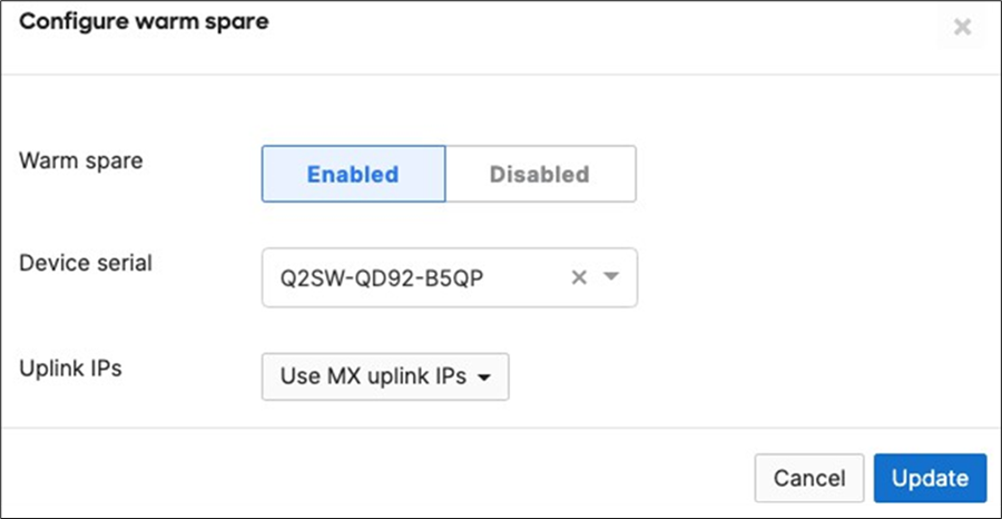
● Now click on Spare to access the Appliance status page of your Spare MX and click on the Edit button to rename the spare unit (e.g. Secondary WAN Edge)


● Then configure the following on your C9500 Core Stack:
| 9500-01#configure terminal 9500-01(config)#interface Twe1/0/2 9500-01(config-if)#switchport mode trunk 9500-01(config-if)#switchport trunk native vlan 3 9500-01(config-if)#switchport trunk allowed vlan 3,100,200,1923 9500-01(config-if)#no shut 9500-01(config-if)#exit 9500-01(config)#interface Twe2/0/2 9500-01(config-if)#switchport mode access 9500-01(config-if)#switchport trunk native vlan 3 9500-01(config-if)#switchport trunk allowed vlan 3,100,200,1923 9500-01(config-if)#no shut 9500-01(config-if)#end 9500-01#wr mem Building configuration... [OK] |
● Then connect the Spare MX downlinks to your C9500 Core Stack (e.g. Spare MX port 19 to Twe1/0/2 and port 20 to Twe2/0/2)
● Then connect the Spare MX with its uplinks (This must match the uplink configuration on your Primary WAN Edge)
● Power on the Spare MX and wait for it to come online on dashboard

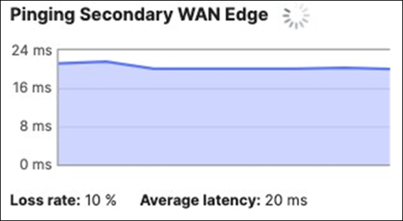
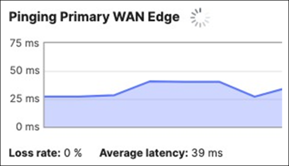
● You can also verify that your C9500 Core Stack interfaces to the Spare MX are up, and that the redundant uplinks are in STP BLK mode
| 9500-01#sh ip interface brief Interface IP-Address OK? Method Status TwentyFiveGigE1/0/2 unassigned YES unset up up TwentyFiveGigE2/0/2 unassigned YES unset up up 9500-01# 9500-01#show spanning-tree MST0 Spanning tree enabled protocol mstp Root ID Priority 4096 Address b0c5.3c60.fba0 This bridge is the root Hello Time 2 sec Max Age 20 sec Forward Delay 15 sec Bridge ID Priority 4096 (priority 4096 sys-id-ext 0) Address b0c5.3c60.fba0 Hello Time 2 sec Max Age 20 sec Forward Delay 15 sec Interface Role Sts Cost Prio.Nbr Type Twe1/0/1 Desg FWD 2000 128.193 P2p Twe1/0/2 Desg FWD 2000 128.194 P2p Twe2/0/1 Back BLK 2000 128.385 P2p Twe2/0/2 Back BLK 2000 128.386 P2p
9500-01# |
40. Access Policy configuration: When you're logged in dashboard, Navigate to Switching > Configure > Access policies to configure Access Policies as required for your Campus LAN. Please see the following example for two Access Policies; 802.1x and MAB.
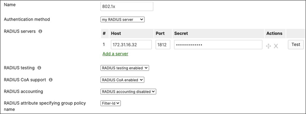
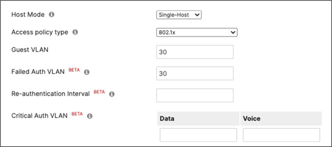
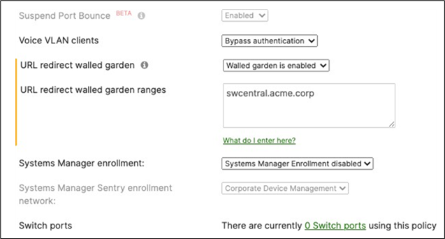
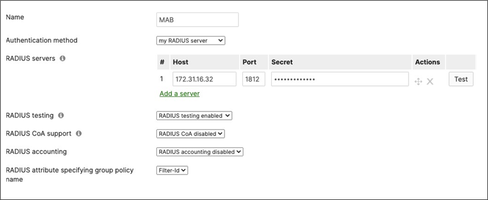
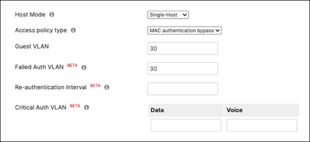
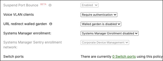
41. Adaptive Policy Configuration: Configure Adaptive Policy for your Campus LAN. When you're logged in dashboard, Navigate to Organization > Configure > Adaptive Policy then click on the Groups tab on the top. There should be two groups (Unknown, Infrastructure) that are already available. Click on Add group to add each group required for your Campus LAN. You need to fill in the Name, the SGT value, and a description then click on Review changes then click on Submit. Please see the following examples.
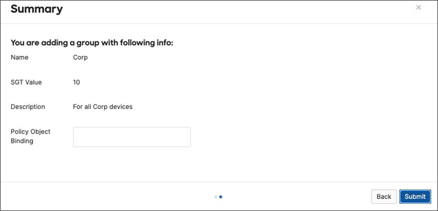
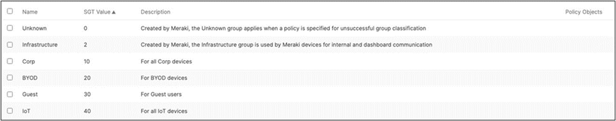
42. Adaptive Policy Configuration: Configure Adaptive Policy for your Campus LAN. When you're logged in dashboard, Navigate to Organization > Configure > Adaptive Policy then click on the Policies tab on the top. The source groups are on the left side, and the destination groups are on the right side. Select a source group from the left side then select all destination groups on the right side that should be allowed then click on Allow and click on Save at the bottom of the page. Next, select a source group from the left side then select all destination groups on the right side that should be denied (i.e. Blocked) then click on Deny and click on Save at the bottom of the page. After creating the policy for that specific source group, the allowed destination groups will be displayed with a green tab and the denied destination groups will be displayed with a red tab. Repeat this step for all policies required for all Groups (Allow and Deny).
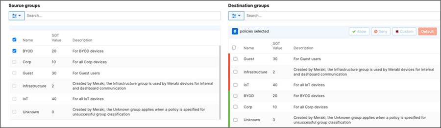
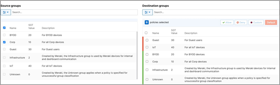
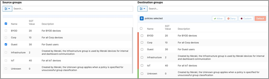
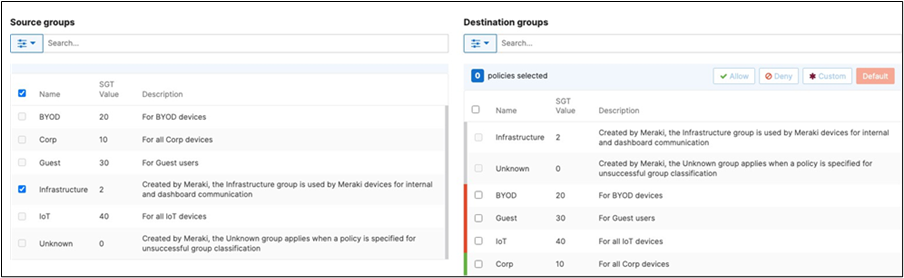
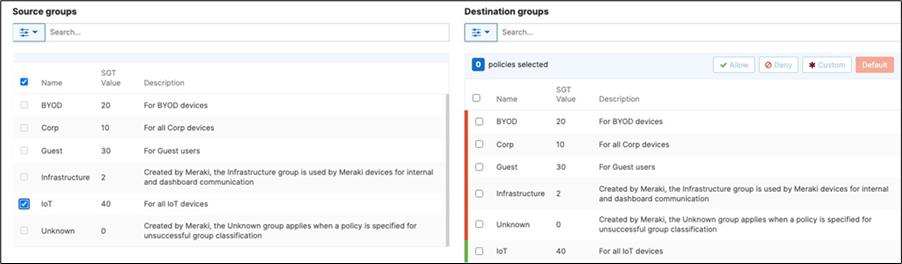
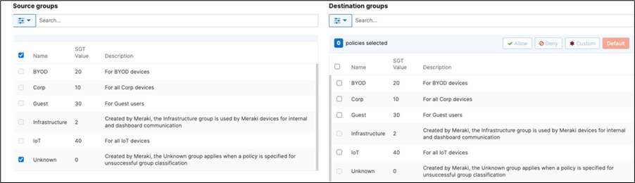
43. Access Switch Ports Preparation: MS390 switches support a maximum of 1000 configured VLANs and given that the default configuration has all switchports in Trunk mode with Native VLAN 1 and allowed VLANs 1-1000 (consuming the 1000 limit already), Dashboard will not allow for the configuration of this design to be saved (i.e. configuring VLAN 1921/1922 as this will breach the 1000 VLANs limit). As such, ports will need to be configured with a different range or VLAN set other than the default settings before applying the configuration needed for this design. It is therefore recommended to configure ALL ports in your network as access in a parking VLAN such as 999. To do that, Navigate to Switching > Monitor > Switch ports then select all ports (Please be mindful of the page overflow and make sure to browse the different pages and apply configuration to ALL ports) and then make sure to deselect stacking ports (as you cannot change configuration on dedicated stacking ports) then click on the Edit button and configure all ports as shown below:
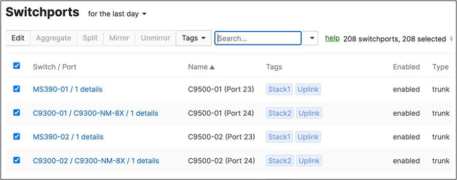
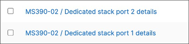
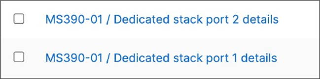
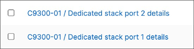
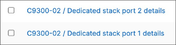
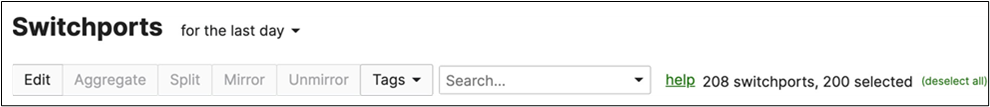
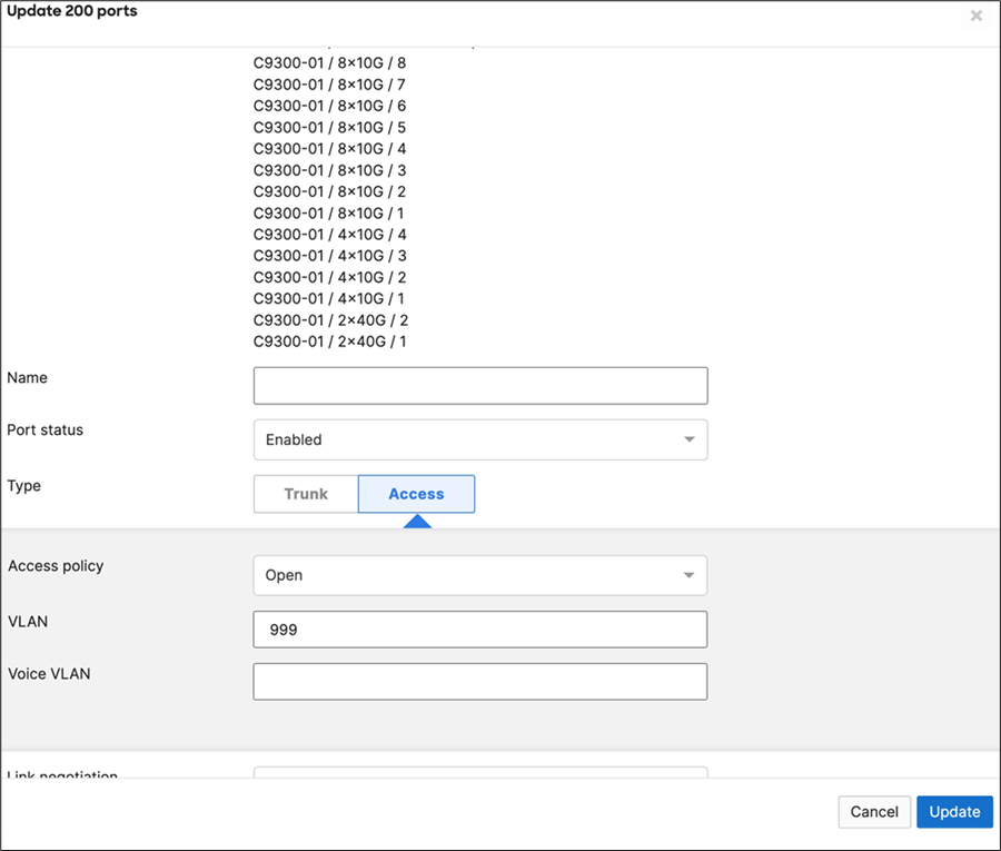
● IMPORTANT - The above step is essential before proceeding to the next steps. If you proceed to the next step and receive an error on Dashboard then it means that some switchports are still configured with the default configuration. Please revisit the Switching > Monitor > Switch ports page and ensure that no ports have a Trunk with allowed VLANs 1-1000
44. Access Switch Ports Configuration: Configure Uplink Ports on your Access Switches. When you're logged in dashboard, Navigate to Switching > Monitor > Switch ports, then select your uplink ports and configure them as shown below. (Tip: You can filter for ports by using search terms in dashboard):
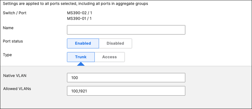
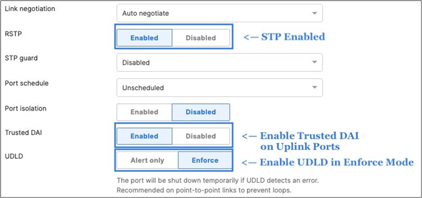
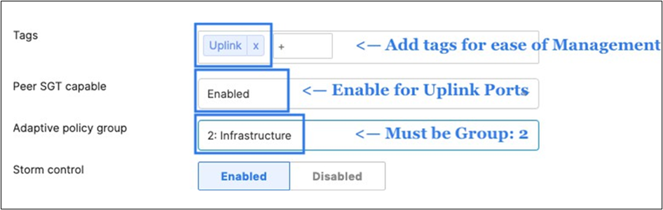
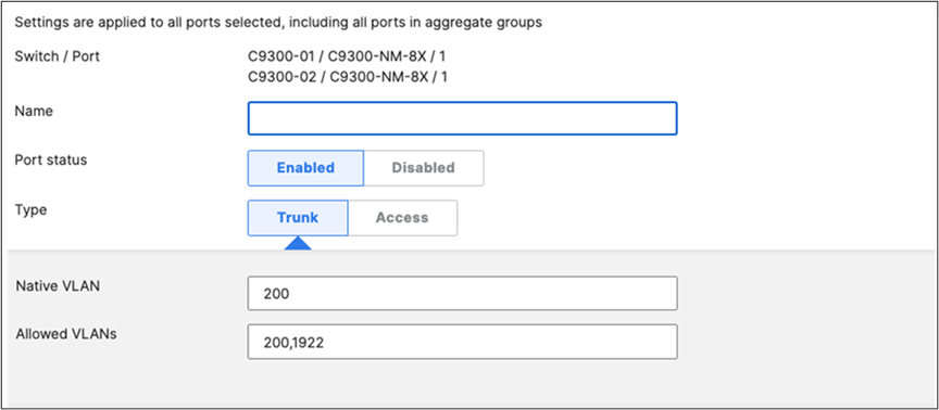
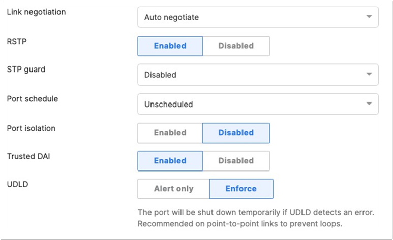
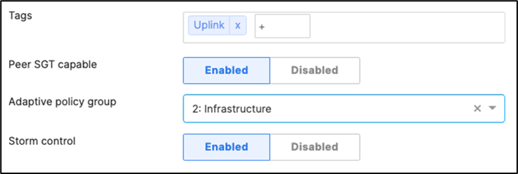
45. Optional - For ease of management, it is recommended that you rename the ports connecting to your Core switches with the actual switch name / Connecting port as shown below.
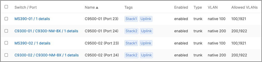
46. Access Switch Ports Configuration: Configure Wired Client Ports (802.1x) on your Access Switches. Navigate to or Refresh Switching > Monitor > Switch Ports, then select your Wired Client ports (5-8) and configure them as◦ shown below. (Tip: You can filter for ports by using search terms in dashboard)

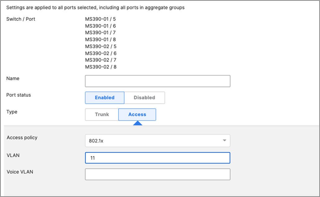
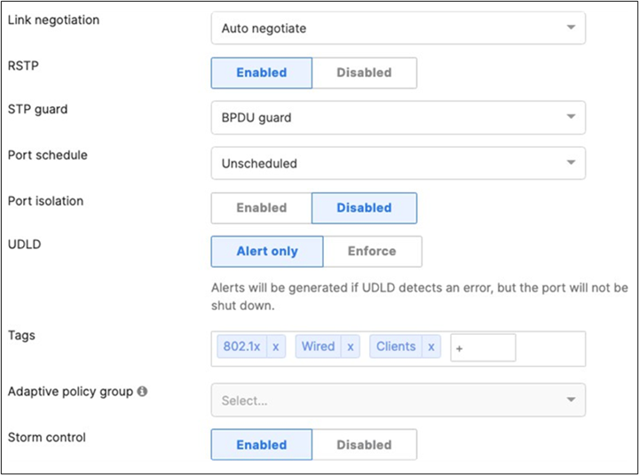
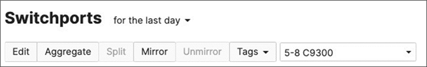
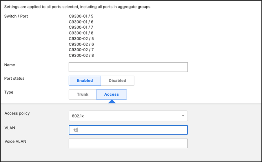
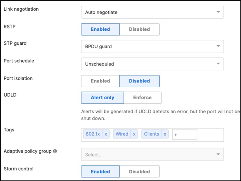
47. Access Switch Ports Configuration: Configure Wired Client Ports (MAB) on your Access Switches. Navigate to or Refresh Switching > Monitor > Switch Ports, then select your Wired Client ports (9-12) and configure them as shown below. (Tip: You can filter for ports by using search terms in dashboard)
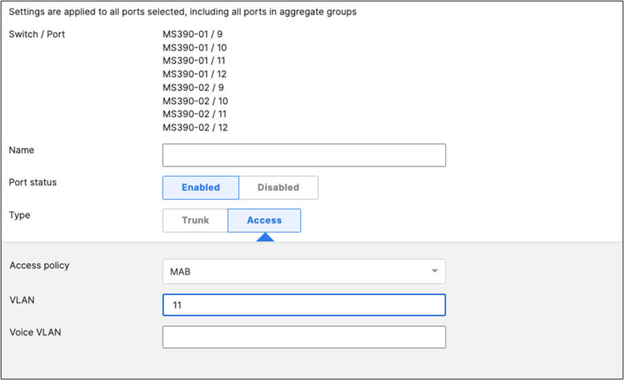
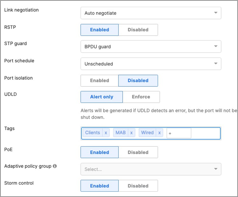
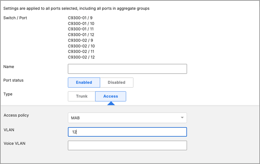
48. Access Switch Ports Configuration: Configure MR Ports on your Access Switches. Navigate to or Refresh Switching > Configure > Switch Ports, then select your ports connecting to MR Access Points (13-16) and configure them as shown below. (Tip: You can filter for ports by using search terms in dashboard)

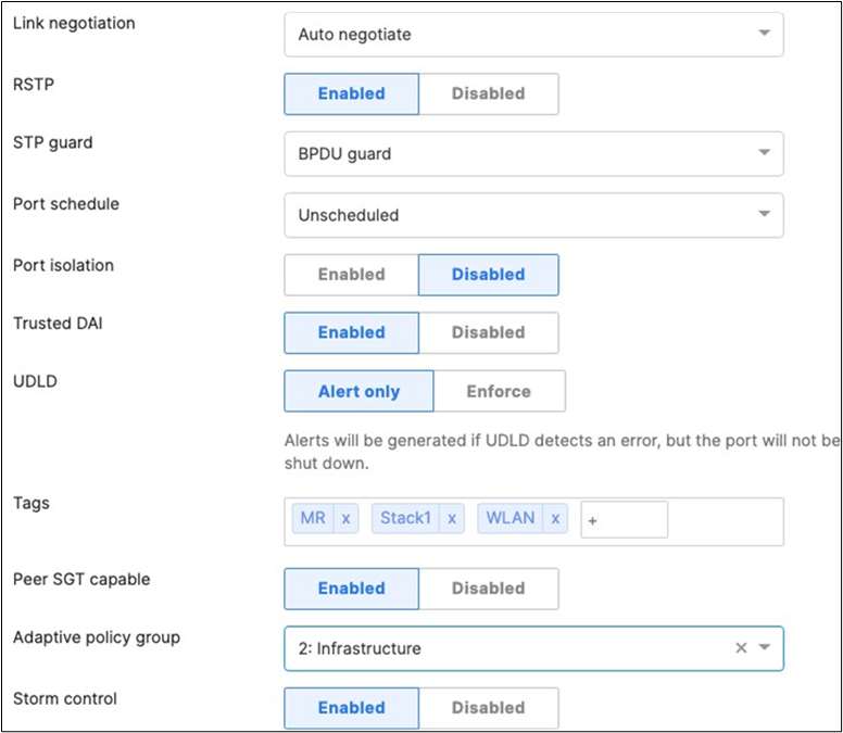
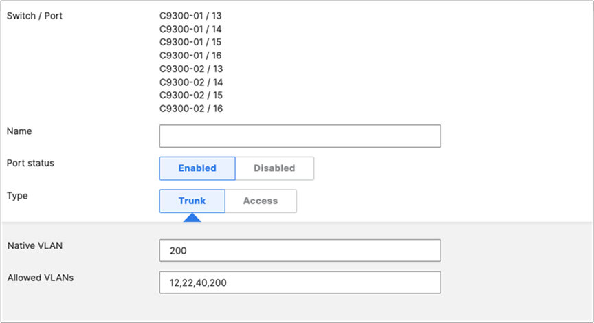
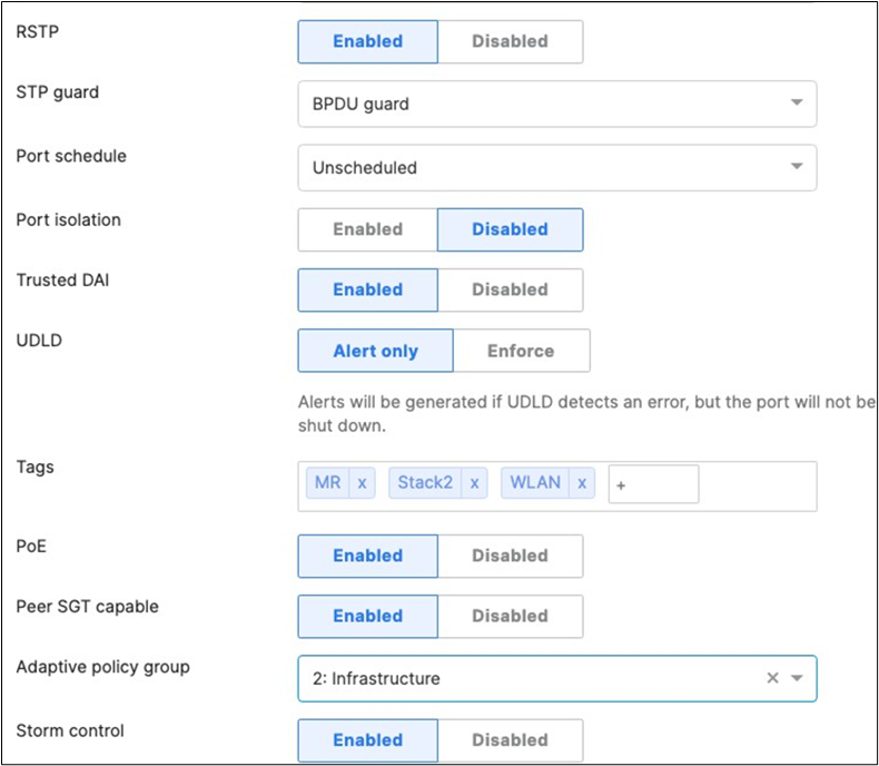
49. Optional - Access Switch Ports Configuration: Configure unused ports on your Access Switches such that they are disabled and mapped to a parking VLAN such as 999. Navigate to Switching > Monitor > Switch Ports and filter for any unused ports (e.g. 17-24) and configure them as shown below.
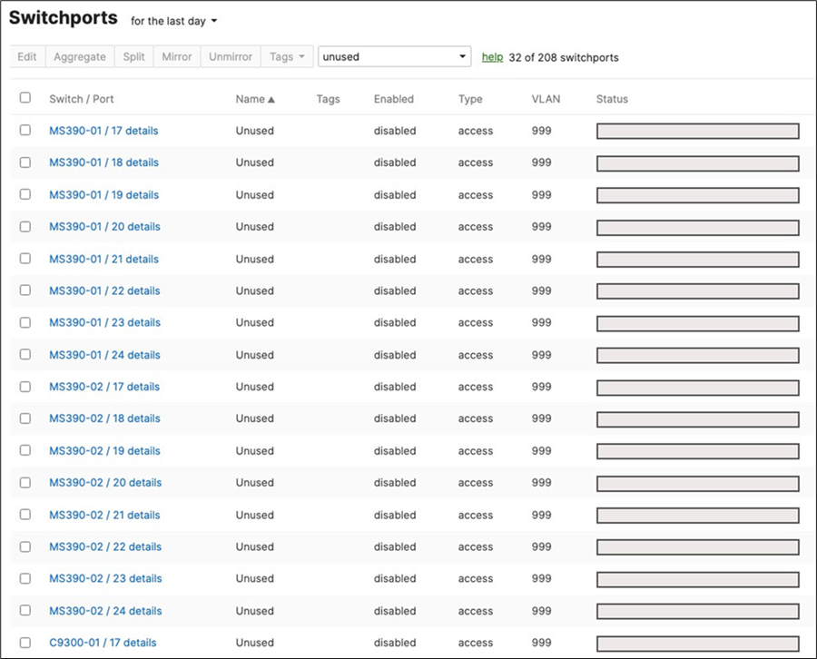
50. Rename Wireless SSIDs: To configure your SSIDs per the above table, first navigate to Wireless > Configure SSIDs then rename the SSIDs per your requirements (Refer to the above table for guidance).
● SSID#1 (First column, aka vap:0, enabled by default): Click on rename and change it to Acme Corp
● SSID#2 (Second column, aka vap:1): Click on rename and change it to Acme BYOD, then click on the top drop-down menu to enable it
● SSID#3 (Third column, aka vap:2): Click on rename and change it to Guest, then click on the top drop-down menu to enable it
● SSID#4 (Fourth column, aka vap:3): Click on rename and change it to Acme IoT, then click on the top drop- down menu to enable it
● Click Save at the bottom of the page
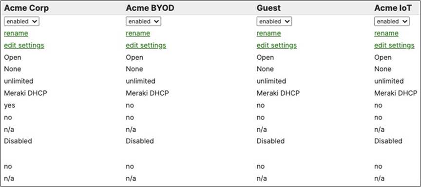
51. Configure Access Control for Acme Corp: Navigate to Wireless > Configure > Access control then from the top drop-down menu choose Acme Corp.

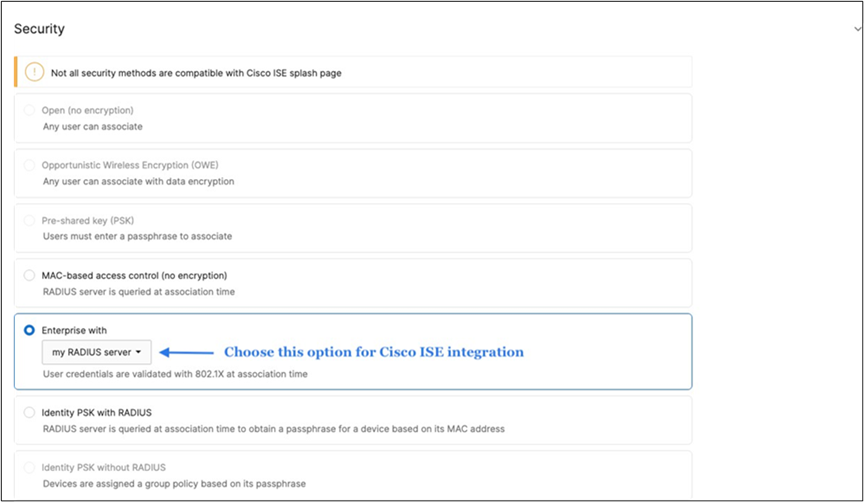
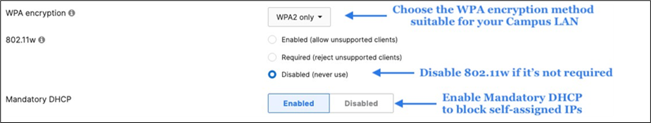
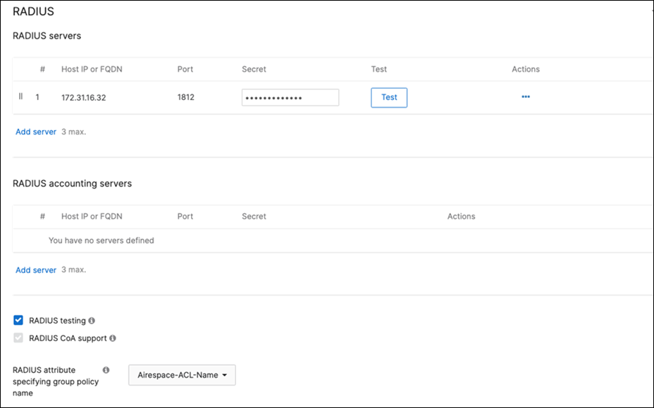
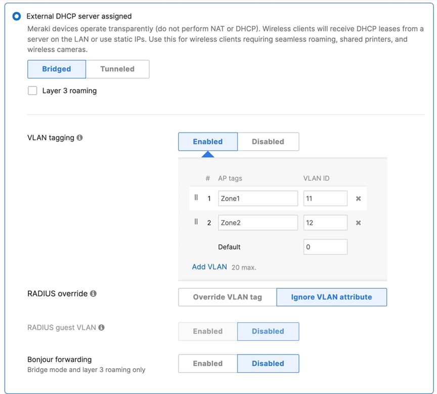
● Click Save at the bottom of the page
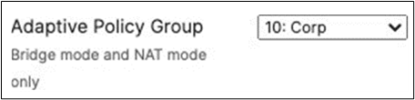
● Please Note: Adaptive Policy Group feature is not currently available in the New Version of the Access. You will need to click on View old version
View old Version
which is available at the top right corner of the page to be able to access this and configure the Adaptive Policy Group (10: Corp). Then, please click Save at the bottom of the page.
52. Configure Access Control for Acme BYOD: Navigate to Wireless > Configure > Access control then from the top drop-down menu choose Acme BYOD.
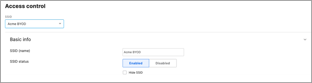
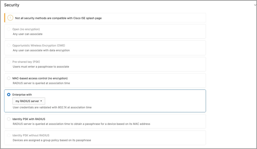
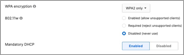
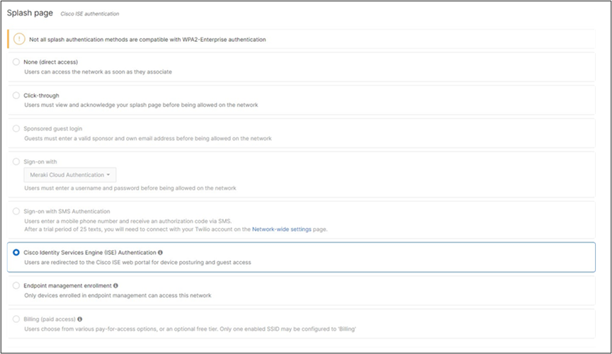
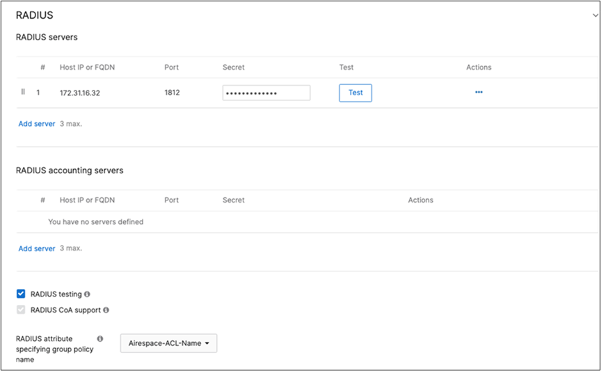
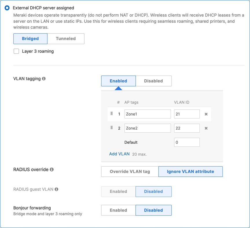
● Click on
View old Version
which is available on the top right corner of the page, then choose the Adaptive Policy Group 20: BYOD and then click on Save at the bottom of the page.
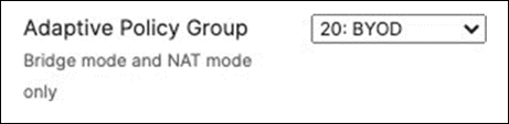
53. Configure Access Control for Guest: Navigate to Wireless > Configure > Access control then from the top drop-down menu choose Guest.
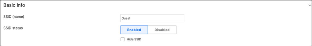
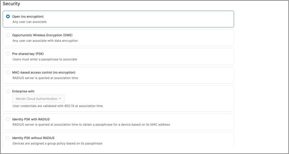
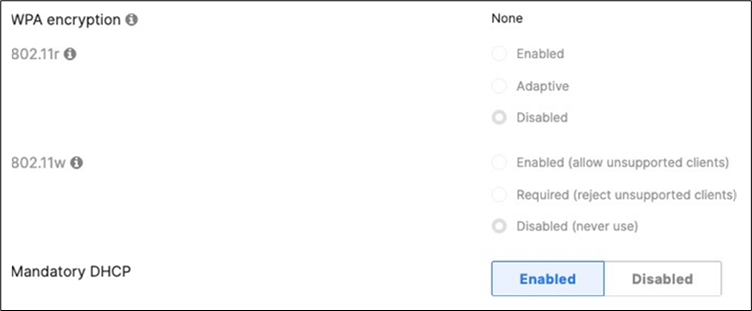
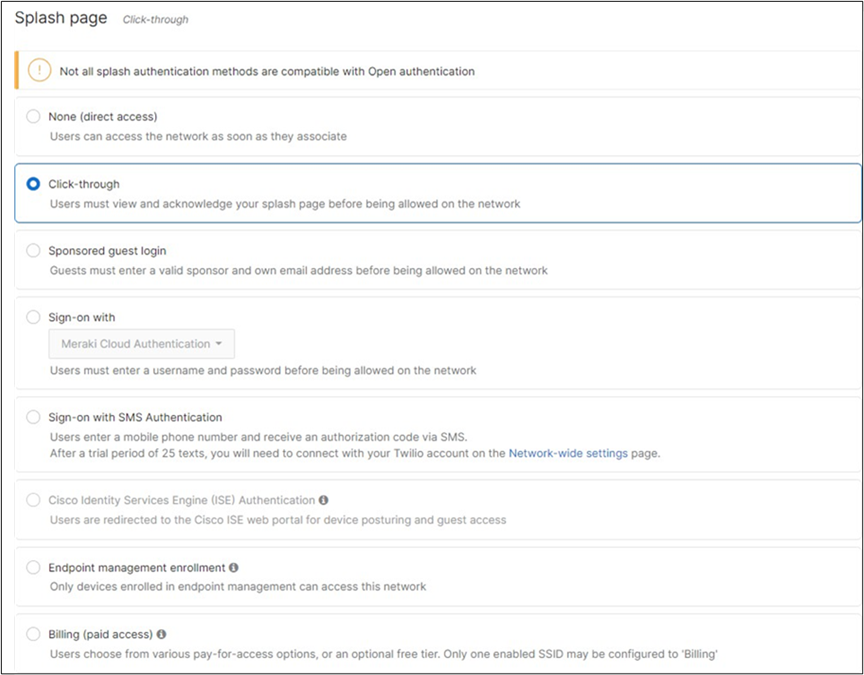
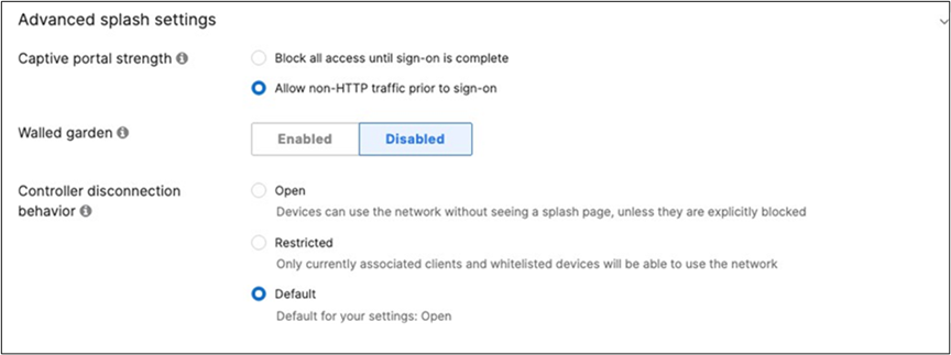
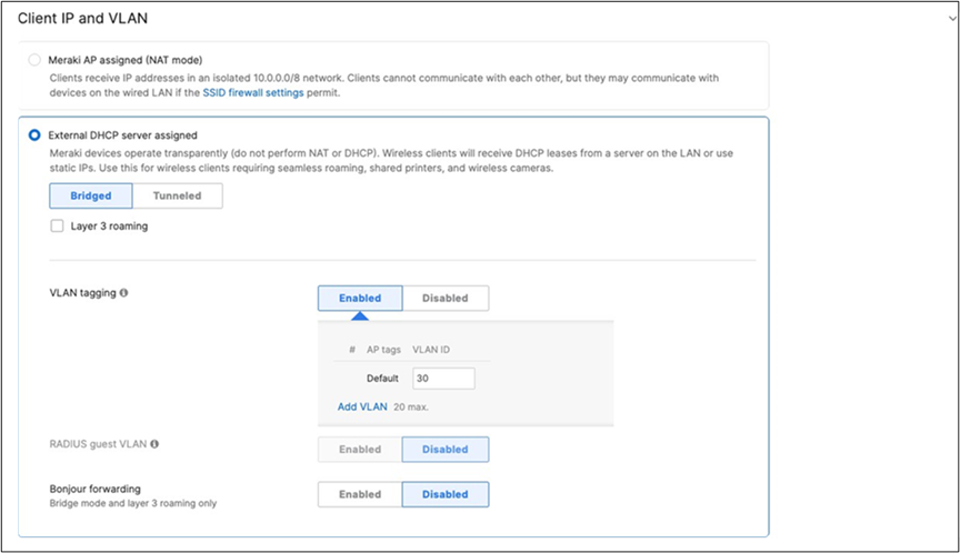
● Click Save at the bottom of the page
● Click on the top right corner of the page on "View Old Version" then choose the Adaptive Policy Group 30:Guest then click on Save at the bottom of the page
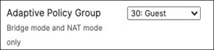
● Navigate to Wireless > Configure > SSID availability and configure broadcast via Tag = Zone 1
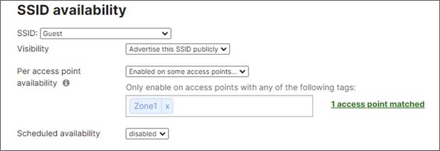
54. Configure Access Control for Acme IoT: Navigate to Wireless > Configure > Access control then from the top drop-down menu choose Acme IoT. (Please note that in this example Acme IoT SSID has been configured with iPSK without Radius).
● Navigate to Network-wide > Configure > Group policies, then create a group policy for IoT devices and click Save at the bottom of the page
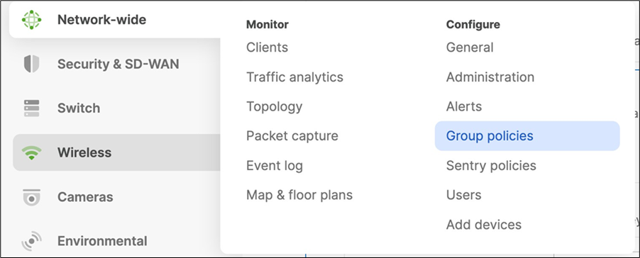
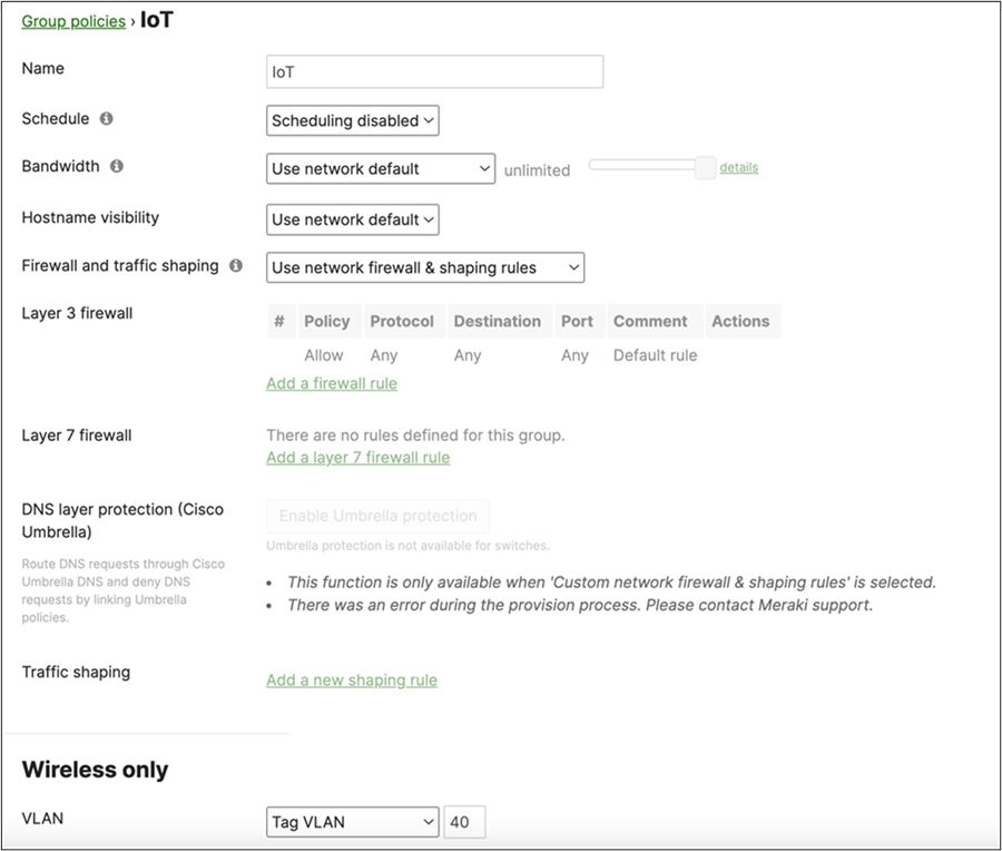
● Then, Navigate to Wireless > Configure > Access control and choose Acme IoT from the top drop-menu and configure settings as shown below, First choose iPSK without Radius from the Security menu:
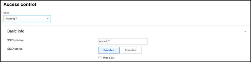

● Then, click on Add an identity PSK:
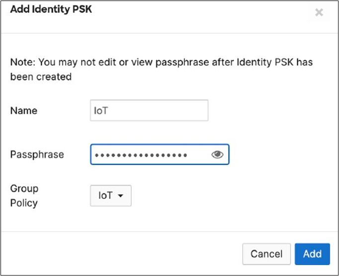
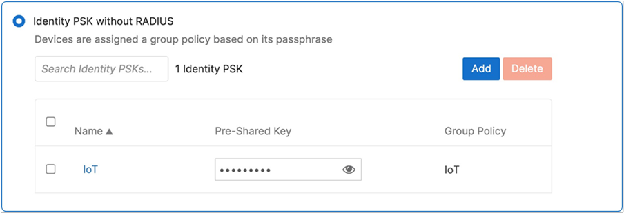
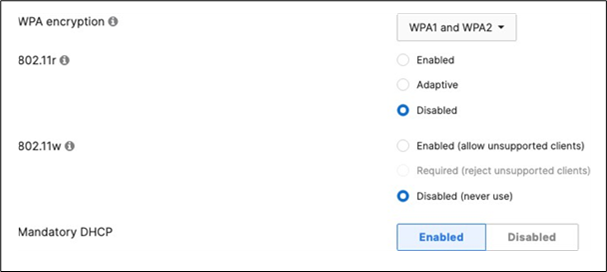
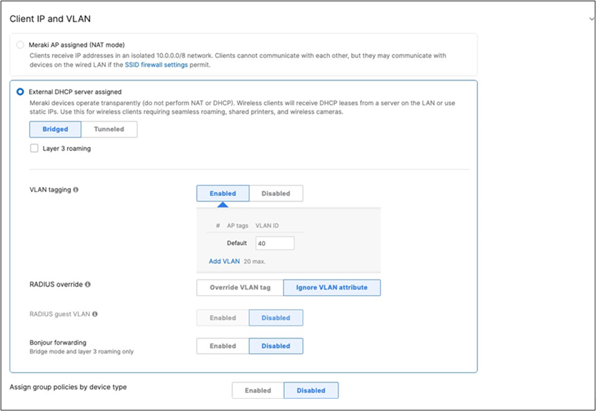
● Click on Save at the bottom of the page
● Click on
View old Version
at the top right corner of the page then choose the Adaptive Policy Group 40: IoT then click on Save at the bottom of the page.
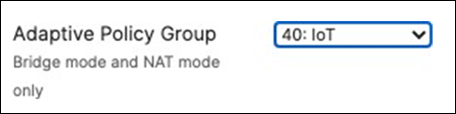
● Navigate to Wireless > Configure > SSID availability and configure broadcast via Tag = Zone 2
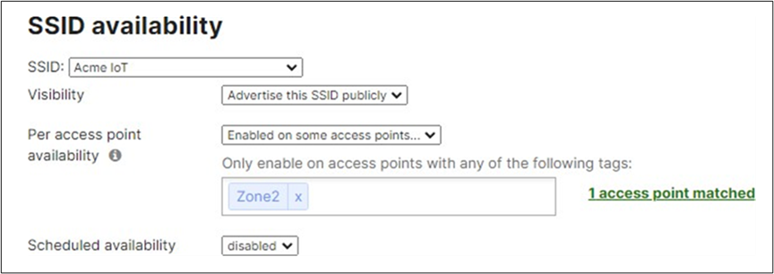
55. Enabling Stacking on your MS390 and C9300 Switches in Meraki Dashboard: Please follow these steps.
A. Connect a single uplink to each switch (e.g. Port 1 on MS390-01 to Port TwentyFiveGigE1/0/23 on C9500)
B. Make sure all stacking cables are unplugged from all switches
C. Power up all switches
D. Verify that your C9500 Stack downlinks are up and not shutdown
| 9500-01#sh ip interface brief Interface IP-Address OK? Method Status Protocol TwentyFiveGigE1/0/23 unassigned YES unset up up TwentyFiveGigE1/0/24 unassigned YES unset up up TwentyFiveGigE2/0/23 unassigned YES unset up up TwentyFiveGigE2/0/24 unassigned YES unset up up 9500-01# |
E. Wait for them to come online on dashboard. Navigate to Switching > Configure > Switches and check the status of your Access Switches
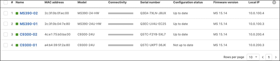
F. After they come online and download their configuration and firmware (Up to date) you can proceed to the next step. You can see their Configuration status and Firmware version from Switching > Configure > Switches
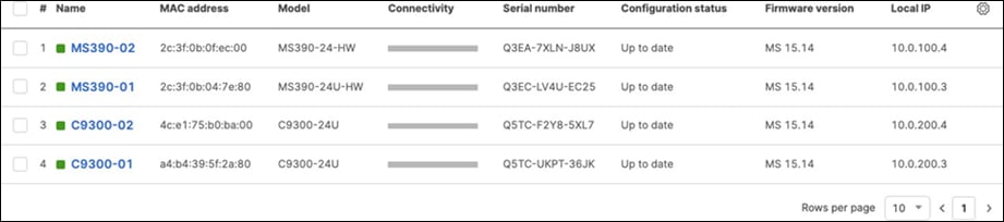
G. Enable stacking in dashboard by Navigating to Switching > Monitor > Switch stacks then click on add one
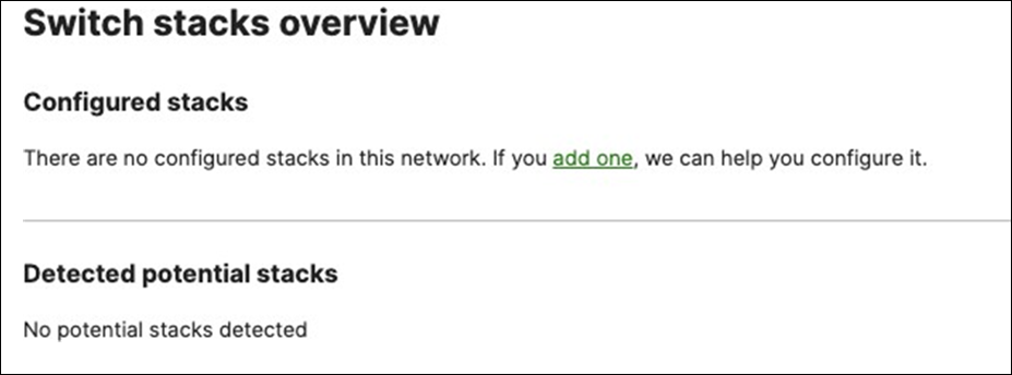
H. Then give your stack a name and select it's members and click on Create


I. Now click on Add a stack to create all other stacks in your Campus LAN access layer by repeating the above steps
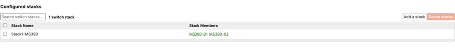
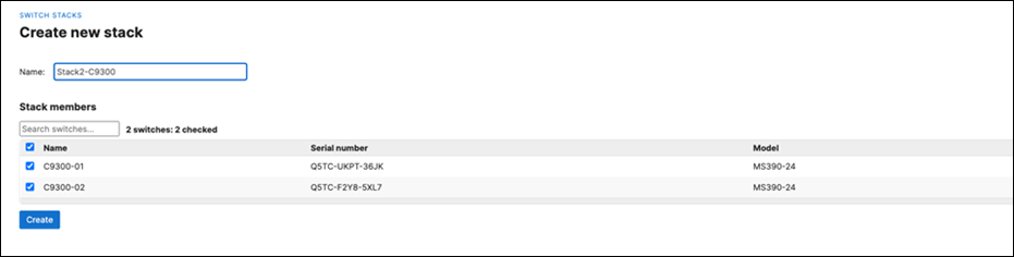
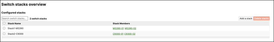
J. Power off all access switches
K. Disconnect all uplink cables from all switches
L. Nominate your master switch for each stack (e.g. MS390-01 for stack1 and C9300-01 for stack2)
M. On the master switches, plug the uplink again
N. Plug stacking cables on all switches in each stack to form a ring topology and make sure that the Cisco logo is upright
O. Power on your master switches first, then power other stack members
P. Wait for the stack to come online on dashboard. To check the status of your stack, Navigate to Switching > Monitor > Switch stacks and then click on each stack to verify that all members are online and that stacking cables show as connected
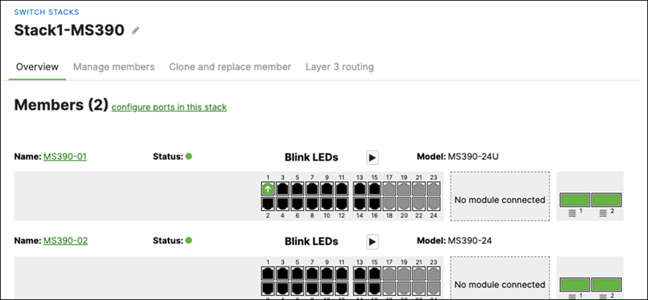
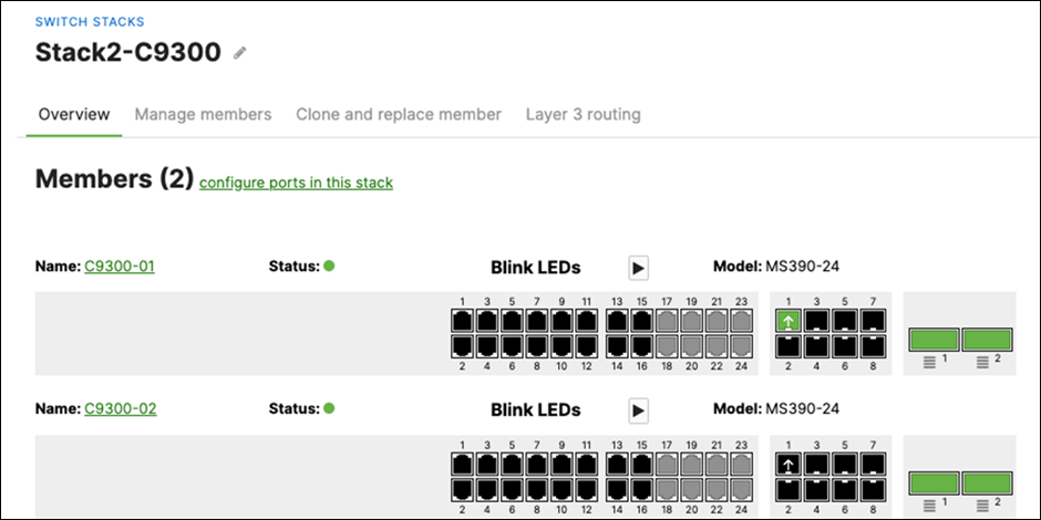
Q. Plug uplinks on all other non-master members and verify that the uplink is online in dashboard by navigating to Switching > Monitor > Switch stacks and then click on each stack to verify that all uplinks are showing as connected however they should be in STP discarding mode.
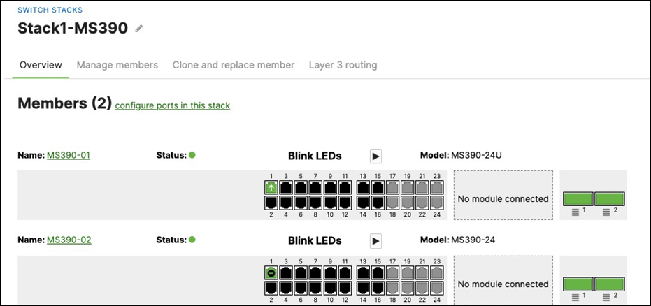
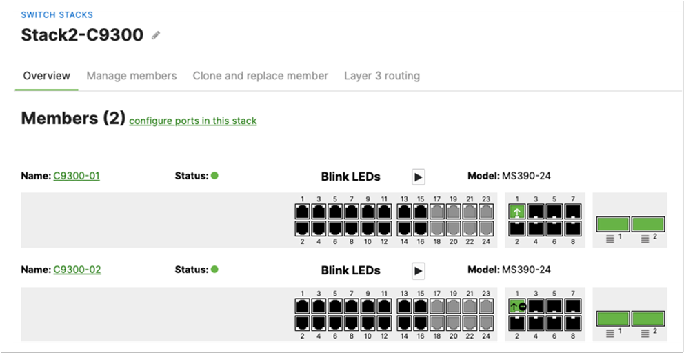
R. Configure the same Static IP for all members in each stack by navigating to Switching > Monitor > Switches then click on the master switch (e.g. MS390-01 for Stack1) and under LAN IP menu copy the IP address then click on the edit button to specify the Static IP address information (You can use the same IP address that was assigned using DHCP) then click Save. The same Static IP address information should now be copied for all members of the same stack. You can verify this by navigating to Switching > Monitor > Switches (Tip: Click on the configure button on the right-hand side of the table to add Local IP information display).
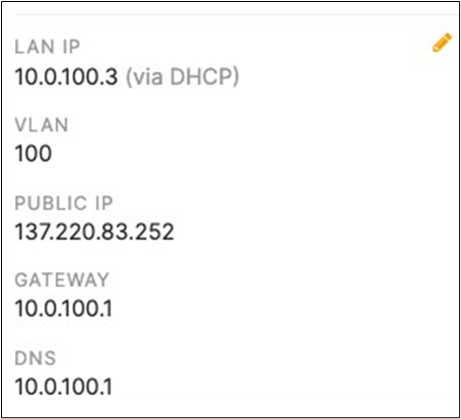
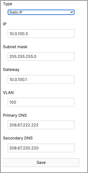
● And on your Stack2-9300 Master Switch:
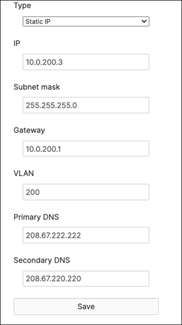
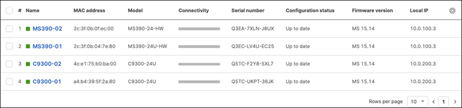
S. Finally, configure etherchannels on both your Access Switch Stacks and your Core Switch Stacks so that all uplinks can be operational (STP forwarding mode) at the same time. Follow these steps:
◦ First, disconnect the downlinks to non-master switches from your C9500 Core Stack (e.g. Port TwentyFiveGigE2/0/23 and TwentyFiveGigE2/0/24)
◦ Navigate to Switching > Monitor > Switch ports and search for uplink then select all uplinks in the same stack (in case you have tagged your ports otherwise search for them manually and select them all) then click on Aggregate. Please note that all port members of the same Ether Channel must have the same configuration otherwise Dashboard will not allow you to click the aggregate button.
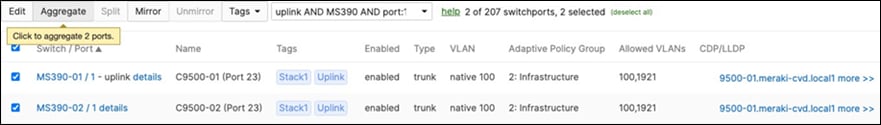

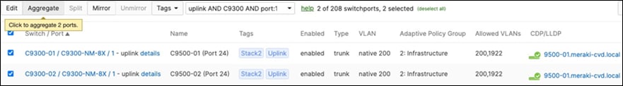

◦ Please repeat above steps for all stacks in your network
◦ Please note that the above step will cause all members within the stack to go offline in Dashboard
● On your C9500 Core Stack, please configure etherchannel Settings for your downlinks such that each Stack downlinks should be in a separate Port-channel and that the mode is active:
| 9500-01#configure terminal Enter configuration commands, one per line. End with CNTL/Z. 9500-01(config)#interface TwentyFiveGigE1/0/23 9500-01(config-if)#channel-group 1 mode active Creating a port-channel interface Port-channel 1
9500-01(config-if)# 9500-01(config-if)#interface TwentyFiveGigE2/0/23 9500-01(config-if)#channel-group 1 mode active 9500-01(config-if)#interface TwentyFiveGigE1/0/24 9500-01(config-if)#channel-group 2 mode active Creating a port-channel interface Port-channel 2
9500-01(config-if)#interface TwentyFiveGigE2/0/24 9500-01(config-if)#channel-group 2 mode active 9500-01(config-if)#end 9500-01# 9500-01#show etherchannel 1 port-channel Port-channels in the group: ------------------------- Port-channel: Po1 (Primary Aggregator) Age of the Port-channel = 0d:01h:42m:43s Logical slot/port = 9/1 Number of ports = 2 HotStandBy port = null Port state = Port-channel Ag-Inuse Protocol = LACP Port security = Disabled Fast-switchover = disabled Fast-switchover Dampening = disabled
Ports in the Port-channel: Index Load Port EC state No of bits ------+------+------+----------------- -+----------- 0 00 Twe1/0/23 Active 0 0 00 Twe2/0/23 Active 0
Time since last port bundled: 0d:01h:40m:21s Twe2/0/23
9500-01# 9500-01#show etherchannel 2 port-channel Port-channels in the group: -------------------------- Port-channel: Po2 (Primary Aggregator) ---------- Age of the Port-channel = 0d:01h:43m:56s Logical slot/port = 9/2 Number of ports = 2 HotStandBy port = null Port state = Port-channel Ag-Inuse Protocol = LACP Port security = Disabled Fast-switchover = disabled Fast-switchover Dampening = disabled
Ports in the Port-channel:
Index Load Port EC state No of bits ------+------+------+--------------+----------- 0 00 Twe1/0/24 Active 0 0 00 Twe2/0/24 Active 0
Time since last port bundled: 0d:01h:42m:04s Twe2/0/24
9500-01#9500-01#wr mem Building configuration...
[OK] 9500-01# |
● Plug all uplinks to non-master switches
● Now all your switches should come back online on Dashboard
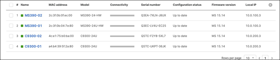
● And now all your uplinks from each stack should be in STP Forwarding mode, which you can verify on Dashboard by navigating to Switching > Monitor > Switch stacks and checking the uplink port status. Also, you can check that on your C9500 Core Stack.
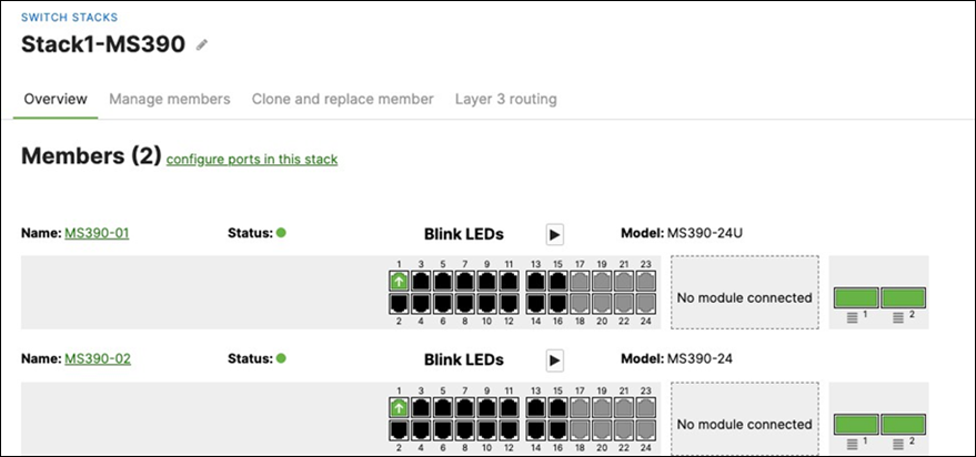
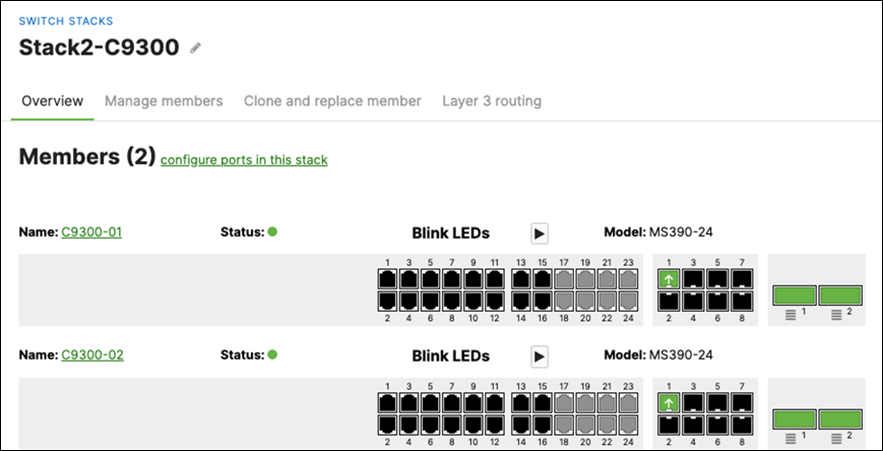
| 9500-01#show spanning-tree interface port-channel 1 Mst Instance Role Sts Cost Prio.Nbr Type ---------------------------------------------------- MST0 Desg FWD 10000 128.2089 P2p 9500-01#show spanning-tree interface port-channel 2
Mst Instance Role Sts Cost Prio.Nbr Type ---------------------------------------------------- MST0 Desg FWD 1000 128.2090 P2p 9500-01#show spanning-tree
MST0 Spanning tree enabled protocol mstp Root ID Priority 4096 Address b0c5.3c60.fba0 This bridge is the root Hello Time 2 sec Max Age 20 sec Forward Delay 15 sec
Bridge ID Priority 4096 (priority 4096 sys-id-ext 0) Address b0c5.3c60.fba0 Hello Time 2 sec Max Age 20 sec Forward Delay 15 sec Interface Role Sts Cost Prio.Nbr Type ------------------------------------------------------ Twe1/0/1 Desg FWD 2000 128.193 P2p Twe2/0/1 Back BLK 2000 128.385 P2p Po1 Desg FWD 10000 128.2089 P2p Po2 Desg FWD 1000 128.2090 P2p
9500-01# |
56. Configure Multiple Spanning Tree Protocol (802.1s) in Dashboard for MS390 and C9300 switches: Navigate to Switch > Configure > Switch settings and select your stack and choose the appropriate STP priority per stack (61440 for all Access Switch Stacks) then click Save at the bottom of the page.
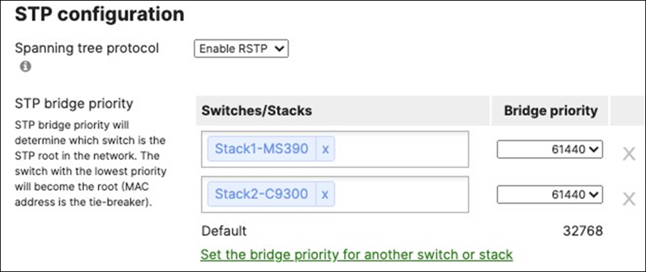
● Please note that changing the STP priority will cause a brief outage as the STP topology will be recalculated.
● Verify that the Access Stacks are seeing the C9500 Core Stack as the root by navigating to Switching > Monitor > Switches then click on any switch and under the RSTP root menu check the root bridge information
57. Configure Dynamic ARP Inspection (DAI) on your C9500 Core Switches: All Downlinks to Access Switches and Uplinks to MX Edge must be configured as Trusted and all other interfaces as Untrusted. (Please note that the order of commands is important to avoid loss of connectivity)
| 9500-01#show cdp neighbors Capability Codes: R - Router, T - Trans Bridge, B - Source Route Bridge S - Switch, H - Host, I - IGMP, r - Repeater, P - Phone, D - Remote, C - CVTA, M - Two-port Mac Relay
Device ID Local Intrfce Holdtme Capability Platform Port ID a4b4395f2a80 Twe 1/0/24 124 S C9300-24U Port C9300-NM-8X/1 2c3f0b0fec00 Twe 2/0/23 174 S MS390-24 Port 1 2c3f0b047e80 Twe 1/0/23 159 S MS390-24U Port 1 4ce175b0ba00 Twe 2/0/24 177 S C9300-24U Port C9300-NM-8X/1
Total cdp entries displayed : 4 9500-01#configure terminal 9500-01(config)#interface TwentyFiveGigE1/0/1 9500-01(config-if)#ip arp inspection trust 9500-01(config-if)#ip dhcp snooping trust 9500-01(config-if)#exit 9500-01(config)#interface TwentyFiveGigE1/0/2 9500-01(config-if)#ip arp inspection trust 9500-01(config-if)#ip dhcp snooping trust 9500-01(config-if)#exit 9500-01(config)#interface TwentyFiveGigE2/0/1 9500-01(config-if)#ip arp inspection trust 9500-01(config-if)#ip dhcp snooping trust 9500-01(config-if)#exit 9500-01(config)#interface TwentyFiveGigE2/0/2 9500-01(config-if)#ip arp inspection trust 9500-01(config-if)#ip dhcp snooping trust 9500-01(config-if)#exit 9500-01(config)#interface Po1 9500-01(config-if)#ip arp inspection trust 9500-01(config-if)#ip dhcp snooping trust 9500-01(config-if)#exit 9500-01(config)#interface Po2 9500-01(config-if)#ip arp inspection trust 9500-01(config-if)#ip dhcp snooping trust 9500-01(config-if)#exit 9500-01(config)#ip arp inspection vlan 3,100,200,1921,1922,1923 9500-01(config)#ip arp inspection validate src-mac 9500-01(config)#ip arp inspection validate ip src-mac 9500-01(config)#ip dhcp snooping vlan 3,100,200, 1921,1922,1923 9500-01(config)#end 9500-01#show ip dhcp snooping Switch DHCP snooping is enabled Switch DHCP gleaning is disabled DHCP snooping is configured on following VLANs: 3,100,200,1921-1923 DHCP snooping is operational on following VLANs: 3,100,200,1921-1923 DHCP snooping is configured on the following L3 Interfaces:
Insertion of option 82 is enabled circuit-id default format: vlan-mod-port remote-id: b0c5.3c60.fba0 (MAC) Option 82 on untrusted port is not allowed Verification of hwaddr field is enabled Verification of giaddr field is enabled DHCP snooping trust/rate is configured on the following Interfaces:
Interface Trusted Allow option Rate limit (pps) ------------------------------------------------------------------- TwentyFiveGigE1/0/1 yes yes unlimited Custom circuit-ids: TwentyFiveGigE1/0/2 yes yes unlimited Custom circuit-ids: TwentyFiveGigE1/0/23 yes yes unlimited Custom circuit-ids: TwentyFiveGigE1/0/24 yes yes unlimited Custom circuit-ids: TwentyFiveGigE2/0/1 yes yes unlimited Custom circuit-ids: TwentyFiveGigE2/0/2 yes yes unlimited Custom circuit-ids: TwentyFiveGigE2/0/23 yes yes unlimited Custom circuit-ids: TwentyFiveGigE2/0/24 yes yes unlimited Custom circuit-ids: Port-channel1 yes yes unlimited Custom circuit-ids: Port-channel2 yes yes unlimited Custom circuit-ids: 9500-01# 9500-01#show ip arp inspection
Source Mac Validation : Enabled Destination Mac Validation : Disabled IP Address Validation : Enable
Vlan Configuration Operation ACL Match Static ACL ----------------------------------------------------- 3 Enabled Active 100 Enabled Active 200 Enabled Active 1921 Enabled Active 1922 Enabled Active 1923 Enabled Active
Vlan ACL Logging DHCP Logging Probe Logging -------------------------------------------------- 3 Deny Deny Off 100 Deny Deny Off 200 Deny Deny Off 1921 Deny Deny Off 1922 Deny Deny Off 1923 Deny Deny Off
Vlan Forwarded Dropped DHCP Drops ACL Drops ------------------------------------------------------------- 3 0 0 0 0 100 0 0 0 0 200 0 0 0 0 1921 0 0 0 0 1922 0 0 0 0 1923 0 0 0 0
Vlan DHCP Permits ACL Permits Probe Permits Source MAC Failures ------------------------------------------------------------------------- 3 0 0 0 0 100 0 0 0 0 200 0 0 0 0 1921 0 0 0 0 1922 0 0 0 0 1923 0 0 0 0
Vlan Dest MAC Failures IP Validation Failures Invalid Protocol Data --------------------------------------------------------------------------- 3 0 0 0 100 0 0 0 200 0 0 0 1921 0 0 0 1922 0 0 0 1923 0 0 0 9500-01#wr mem Building configuration... [OK] 9500-01# |
58. Configure Dynamic Arp Inspection (DAI) on your Access Switch Stacks: Navigate to Switch > Monitor > DHCP Servers and ARP and scroll down to Dynamic ARP Inspection and enable it, then click Save at the bottom of the page.
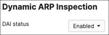
59. Setting up your Access Points: Connect your APs to the respective ports on the Access Switches (e.g. Ports 13-16) and wait for them to come online on dashboard and download their firmware and configuration files. To check the status of your APs navigate to Wireless > Monitor > Access points and check the status, configuration and firmware of your APs.
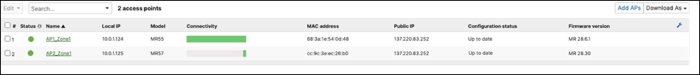
60. Re-addressing your Network Devices: In this step, you will adjust your IP addressing configuration - if required - to align with your network design. This step could have been done earlier in the process however it will be easier to adjust after all your network devices have come online since the MX (The DHCP server for Management VLAN 1) has kept a record of the actual MAC addresses of all DHCP clients. Follow these steps to re-assign the desired IP addresses. (Please note that this will cause disruption to your network connectivity)
A. Navigate to Organization > Monitor > Overview then click on Devices tab to check the current IP addressing for your network devices
B. Navigate to Security and SD-WAN > Monitor > Appliance status then click on the Tools tab and click on Run next to ARP Table
C. Take a note of the MAC addresses of your network devices
D. Navigate to Security and SD-WAN > Configure > DHCP then under Fixed IP assignments click on Add a fixed IP assignment and add entries under each DHCP Pool as shown below for your network devices using the MAC addresses you have from Step #3 above then click on Save at the bottom of the page.
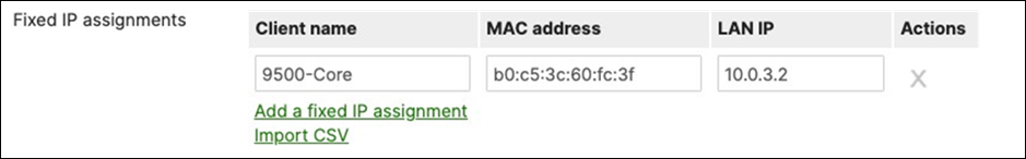
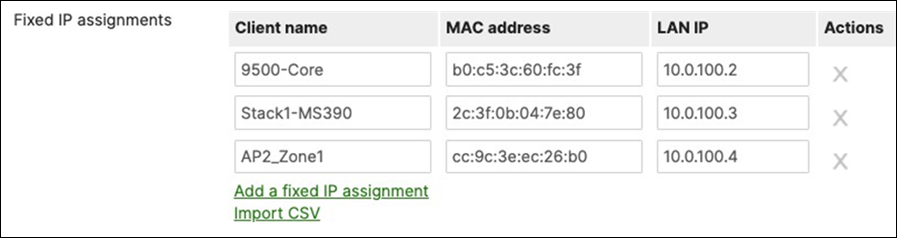
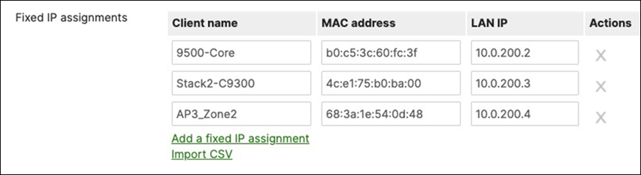
E. Navigate to Switching > Monitor > Switch ports then filter for MR (in case you have previously tagged your ports or select ports manually if you haven't) then select those ports and click on Edit, then set Port status to Disabled then click on Save.


F. After a few minutes (For configuration to be up to date) navigate to Switching > Monitor > Switch ports, then filter for MR (in case you have previously tagged your ports or select ports manually if you haven't) then select those ports and click on Edit, then set Port status to Enabled then click on Save.
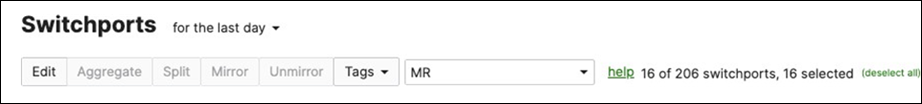

G. Navigate to Switching > Monitor > Switches, then click on each master switch to change its IP address to the one desired using Static IP configuration (remember that all members of the same stack need to have the same static IP address)
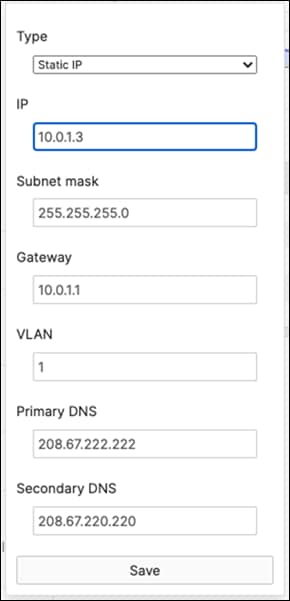
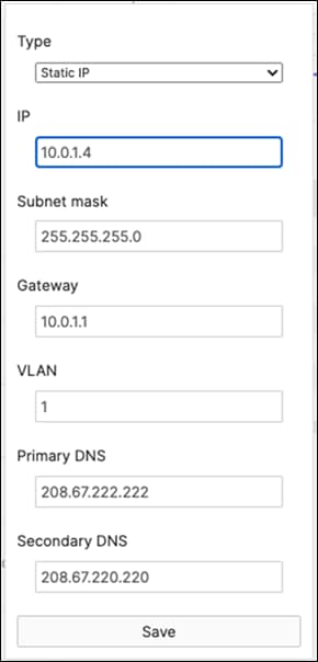
H. On your C9500 Core Stack, bounce your VLAN 3,100,200 interfaces. Then verify that the interfaces VLAN 3/ 100/200 came up with the correct IP address (e.g. 10.0.3.2 per this design)
| 9500-01#configure terminal Enter configuration commands, one per line. End with CNTL/Z. 9500-01(config)#interface vlan 3 9500-01(config-if)#shutdown 9500-01(config-if)#no shutdown 9500-01(config-if)#interface vlan 100 9500-01(config-if)#shutdown 9500-01(config-if)#no shutdown 9500-01(config-if)#interface vlan 200 9500-01(config-if)#shutdown 9500-01(config-if)#no shutdown 9500-01(config-if)#end 9500-01#sh ip interface brief | in Vlan Vlan1 unassigned YES NVRAM administratively down down Vlan3 10.0.3.2 YES DHCP up up Vlan100 10.0.100.2 YES DHCP up up Vlan200 10.0.200.2 YES DHCP up up 9500-01# |
I. Navigate to Organization > Monitor > Overview then click on Devices tab to check the current IP addressing for your network devices:
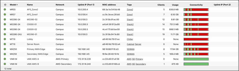
61. Configure QoS in your Campus LAN: Quality of Service configuration needs to be consistent across the whole Campus LAN. Please refer to the above table as an example. (For the purpose of this CVD, Default traffic shaping rules will be used to mark traffic with DSCP values without setting any traffic limits. Please adjust traffic shaping rules based on your own requirements). To configure QoS, please follow these steps.
A. Navigate to Wireless > Configure > Firewall and Traffic Shaping and choose the Acme Corp SSID from the above drop-down menu. Under Traffic Shaping rules, choose the per-client and per-SSID limits desired and select Shape traffic on this SSID then select Enable default traffic shaping rules. Click Save at the bottom of the page when you are done. Click Save at the bottom of the page when you are done.
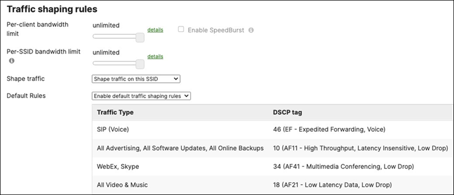
B. Navigate to Wireless > Configure > Firewall and Traffic Shaping and choose the Acme BYOD SSID from the above drop-down menu. Under Traffic Shaping rules, choose the per-client and per-SSID limits desired and select Shape traffic on this SSID then select Enable default traffic shaping rules.
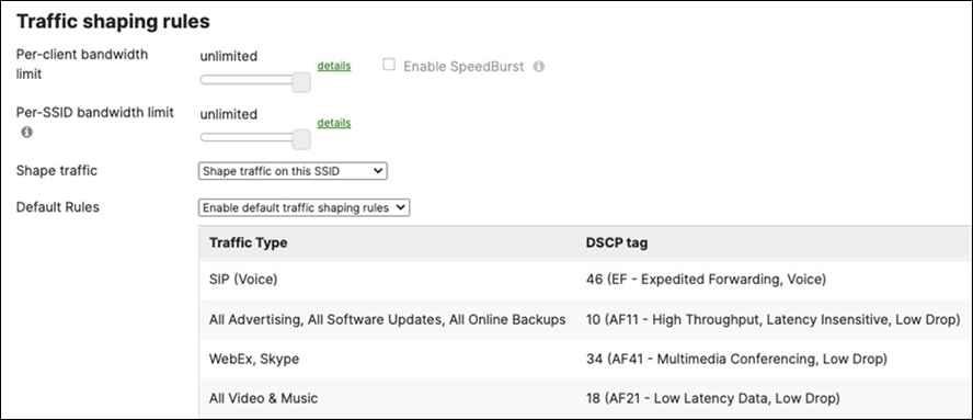
C. Navigate to Wireless > Configure > Firewall and Traffic Shaping and choose the Guest SSID from the above drop-down menu. Under Traffic Shaping rules, choose the per-client and per-SSID limits desired and select Shape traffic on this SSID then select Enable default traffic shaping rules. Click Save at the bottom of the page when you are done.

D. Navigate to Wireless > Configure > Firewall and Traffic Shaping and choose the IoT SSID from the above drop-down menu. Under Traffic Shaping rules, choose the per-client and per-SSID limits desired and select Shape traffic on this SSID then select Enable default traffic shaping rules. Click Save at the bottom of the page when you are done.
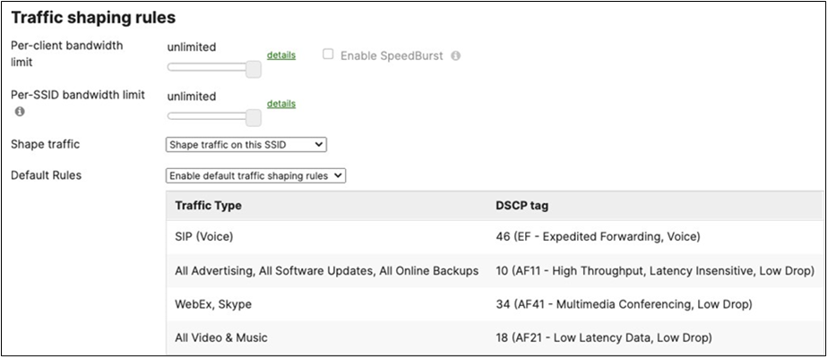
E. Navigate to Switching > Configure > Switch settings and under the Quality of Service menu configure the VLAN to DSCP mappings. Please click on Edit DSCP to CoS map to change settings per your requirements. Click Save at the bottom of the page when you are done. (Please note that the ports used in the below example are based on Cisco Webex traffic flow)
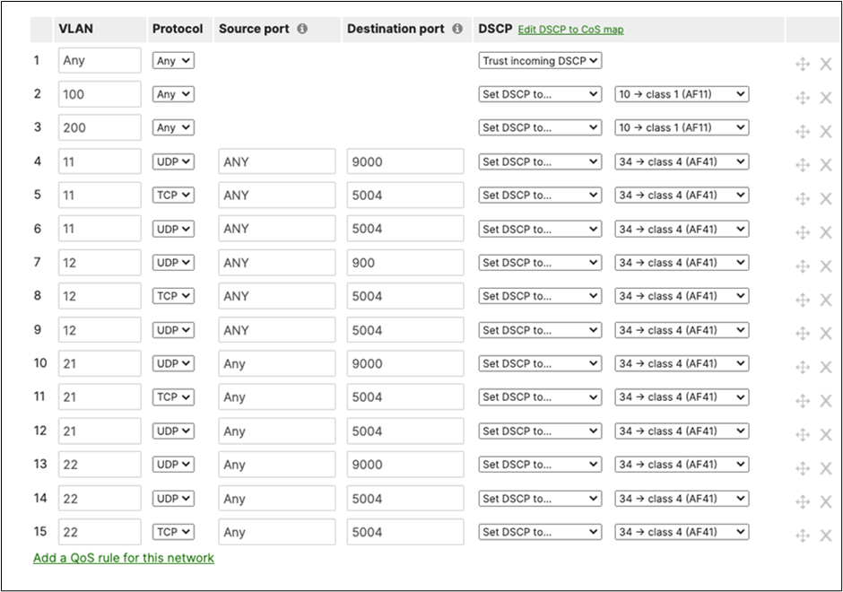
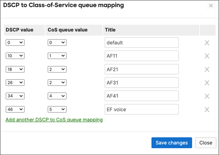
F. Please ensure that your C9500 Core Stack is configured to trust incoming QoS. Here's a reference of the configuration needed to be applied:
| 9500-01#configure terminal Enter configuration commands, one per line. End with CNTL/Z. 9500-01(config)#interface TwentyFiveGigE1/0/1 9500-01(config-if)#auto qos trust dscp 9500-01(config-if)#interface TwentyFiveGigE1/0/2 9500-01(config-if)#auto qos trust dscp 9500-01(config-if)#interface TwentyFiveGigE2/0/1 9500-01(config-if)#auto qos trust dscp 9500-01(config-if)#interface TwentyFiveGigE2/0/2 9500-01(config-if)#auto qos trust dscp 9500-01(config-if)#interface TwentyFiveGigE1/0/23 9500-01(config-if)#auto qos trust dscp Warning: add service policy will cause inconsistency with port TwentyFiveGigE2/0/23 in ether channel 1. 9500-01(config-if)#interface TwentyFiveGigE1/0/24 9500-01(config-if)#auto qos trust dscp Warning: add service policy will cause inconsistency with port TwentyFiveGigE2/0/24 in ether channel 2. 9500-01(config-if)#interface TwentyFiveGigE1/0/24 9500-01(config-if)#auto qos trust dscp 9500-01(config-if)#end 9500-01#show auto qos TwentyFiveGigE1/0/1 auto qos trust dscp
TwentyFiveGigE1/0/2 auto qos trust dscp
TwentyFiveGigE1/0/23 auto qos trust dscp
TwentyFiveGigE1/0/24 auto qos trust dscp
TwentyFiveGigE2/0/1 auto qos trust dscp
TwentyFiveGigE2/0/2 auto qos trust dscp
TwentyFiveGigE2/0/23 auto qos trust dscp
TwentyFiveGigE2/0/24 auto qos trust dscp
9500-01#wr mem |
G. Navigate to Security and SD-WAN > Configure > SD-WAN and Traffic shaping and make sure your Uplink configuration matches your WAN speed. Then, under Uplink selection choose the settings that match your requirements (e.g. Load balancing). Under Traffic shaping rules, select Enable default traffic shaping rules then click on Add a new shaping rule to create the rules needed for your network. (for more information about Traffic shaping rules on MX appliances, please refer to the following article). Please see the following example:
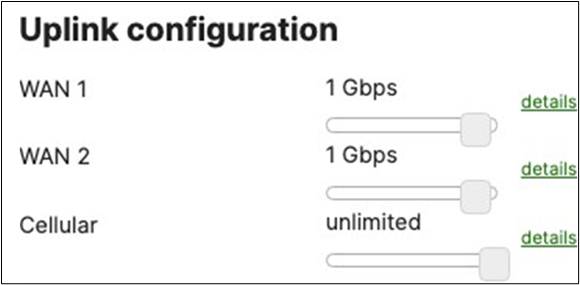
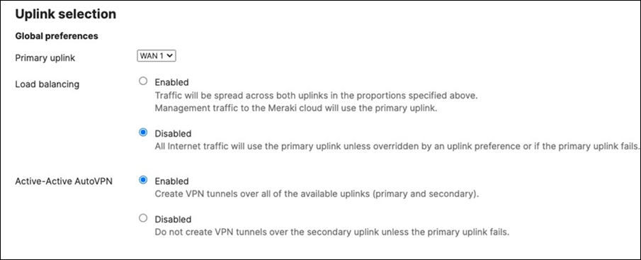
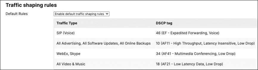

62. Enable OSPF Routing: Navigate to Switching > Configure > OSPF routing and then click on Enabled to enable OSPF. Add the details required and create an OSPF area for your Campus Network. Then, click Save at the bottom of the page.
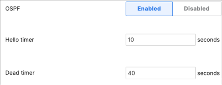
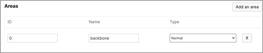
63. Enable OSPF Routing on your Core Stack: Please use the following commands to add an OSPF instance and create OSPF neighbors.
| 9500-01#configure terminal Enter configuration commands, one per line. End with CNTL/Z. 9500-01(config)#router ospf 1 9500-01(config-router)#network 192.168.1.0 0.0.0.255 area 0 9500-01(config-router)#network 192.168.2.0 0.0.0.255 area 0 9500-01(config-router)#neighbor 192.168.1.1 9500-01(config-router)#neighbor 192.168.2.1 9500-01(config-router)#end 9500-01# 9500-01#show ip ospf neighbor Neighbor ID Pri State Dead Time Address Interface 192.168.2.2 1 FULL/DR 00:00:33 192.168.2.2 Vlan1922 192.168.1.2 1 FULL/DR 00:00:38 192.168.1.2 Vlan1921 9500-01#wr mem |
64. Create SVI Interfaces on your Access Switch Stacks: Navigate to Switching > Configure > Routing and DHCP and click on CREATE INTERFACE and start adding your interfaces but first start with the Transit VLANs. Once you have created an interface click on Save and add another at the bottom of the page to add more interfaces.
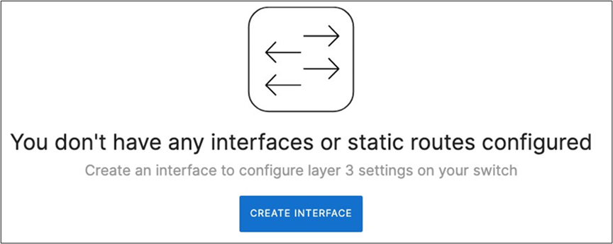
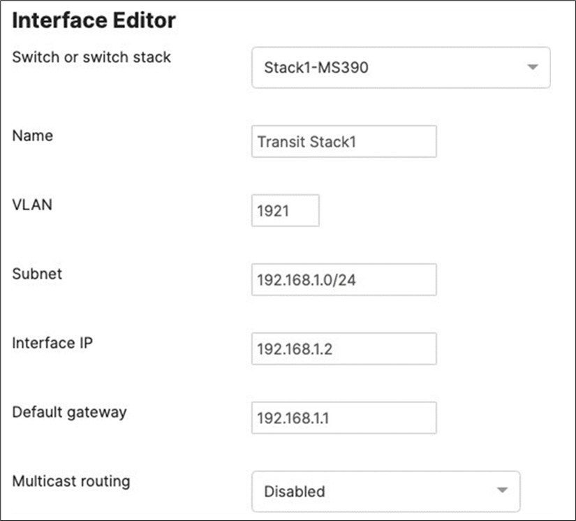

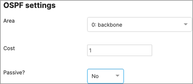
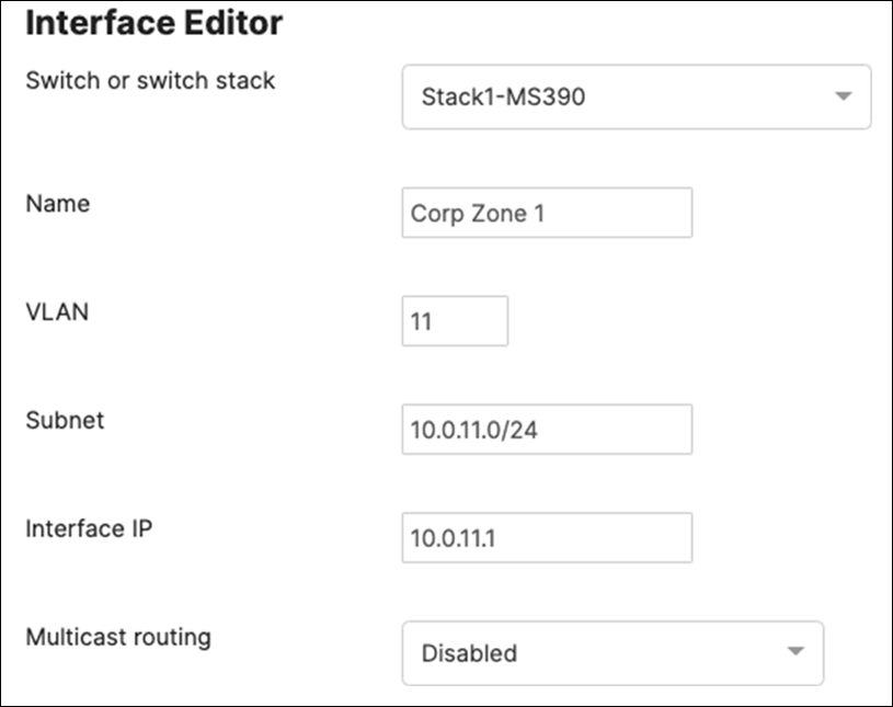
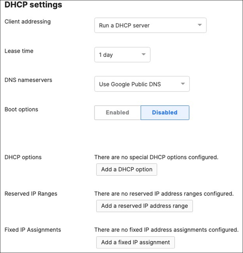
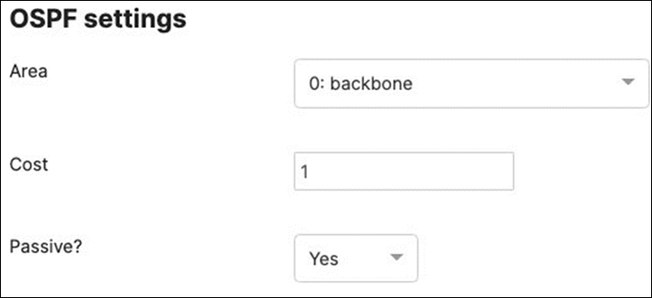
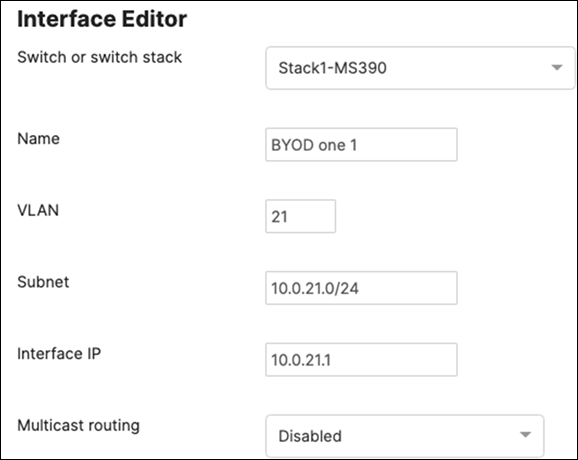
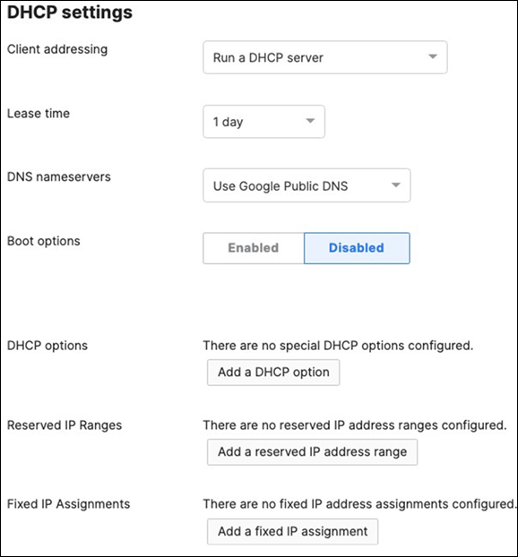
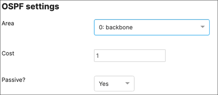
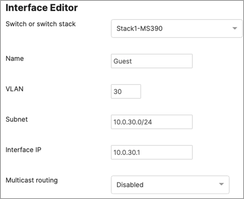
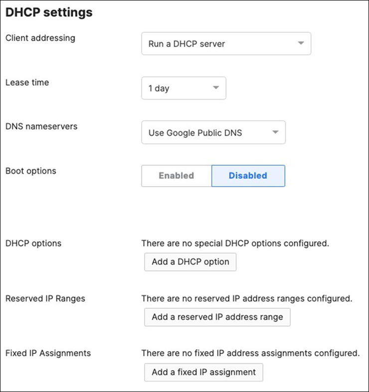

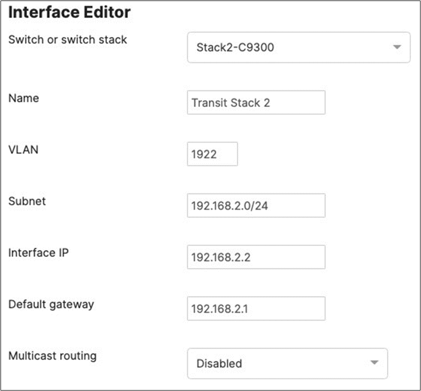
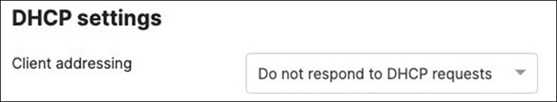

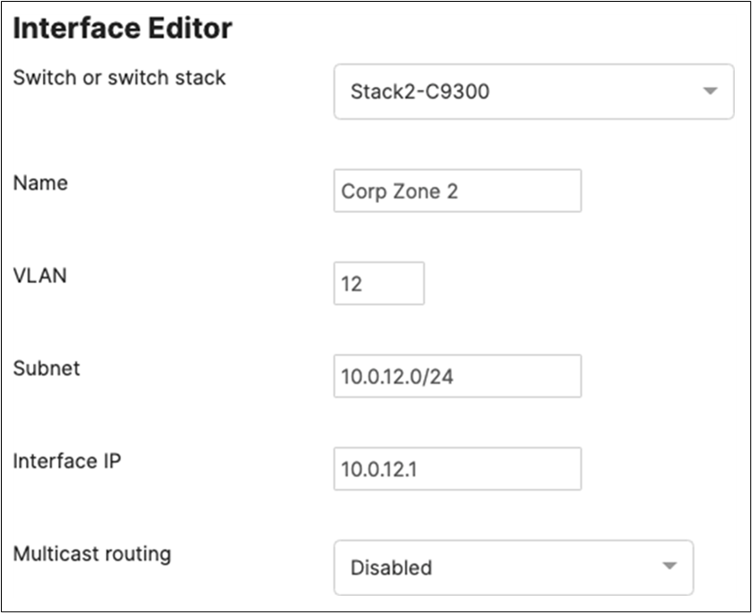
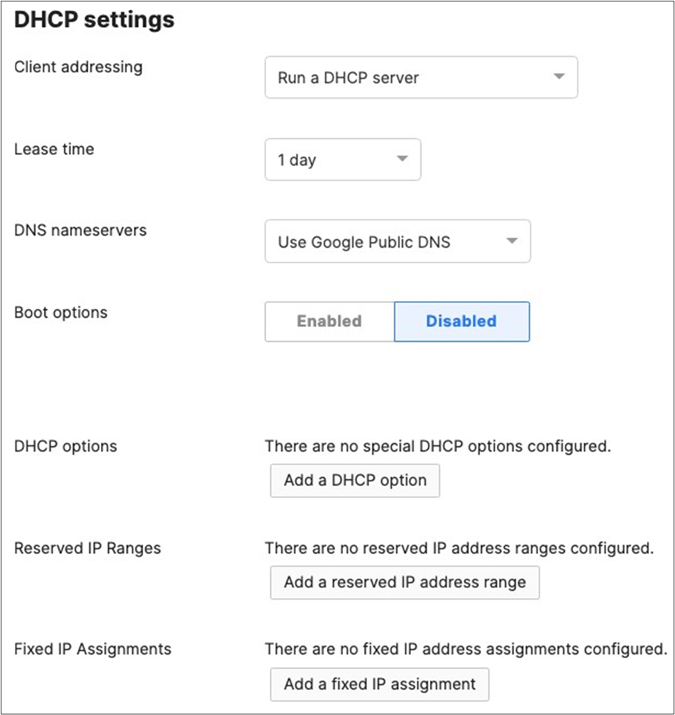
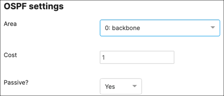
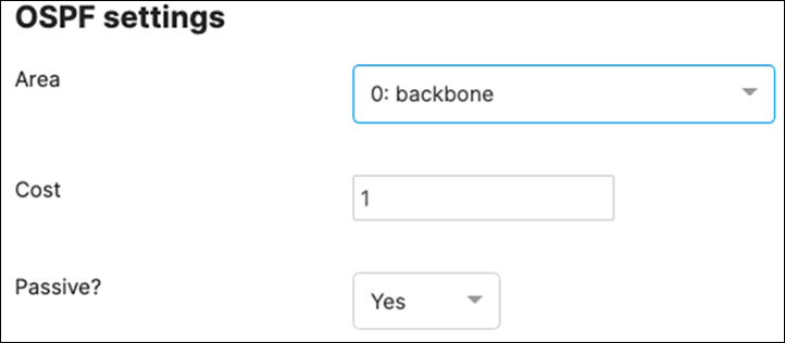
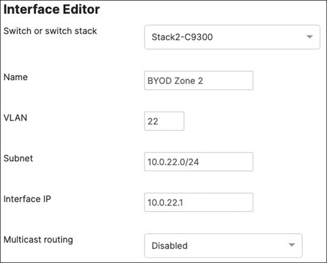
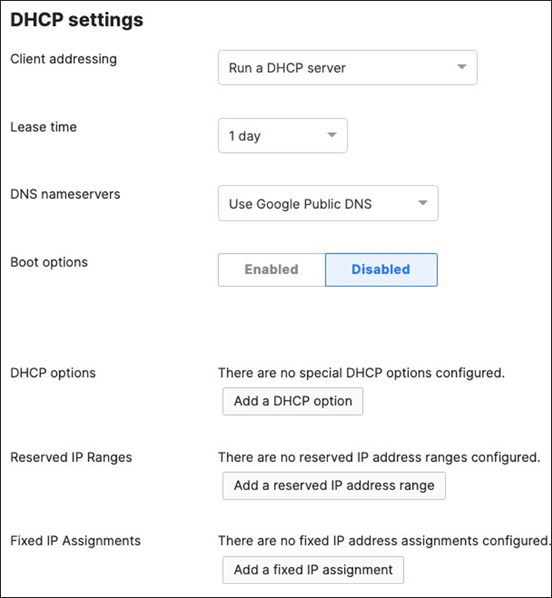
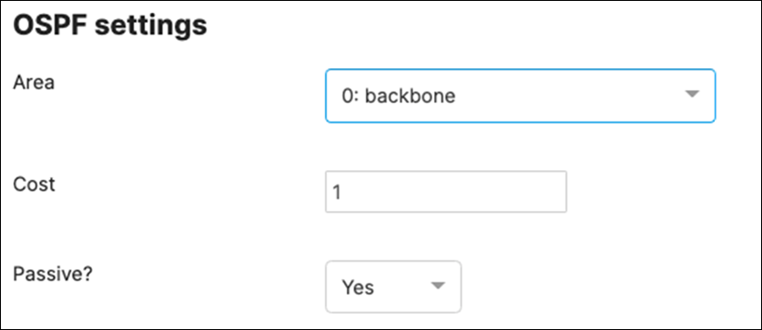

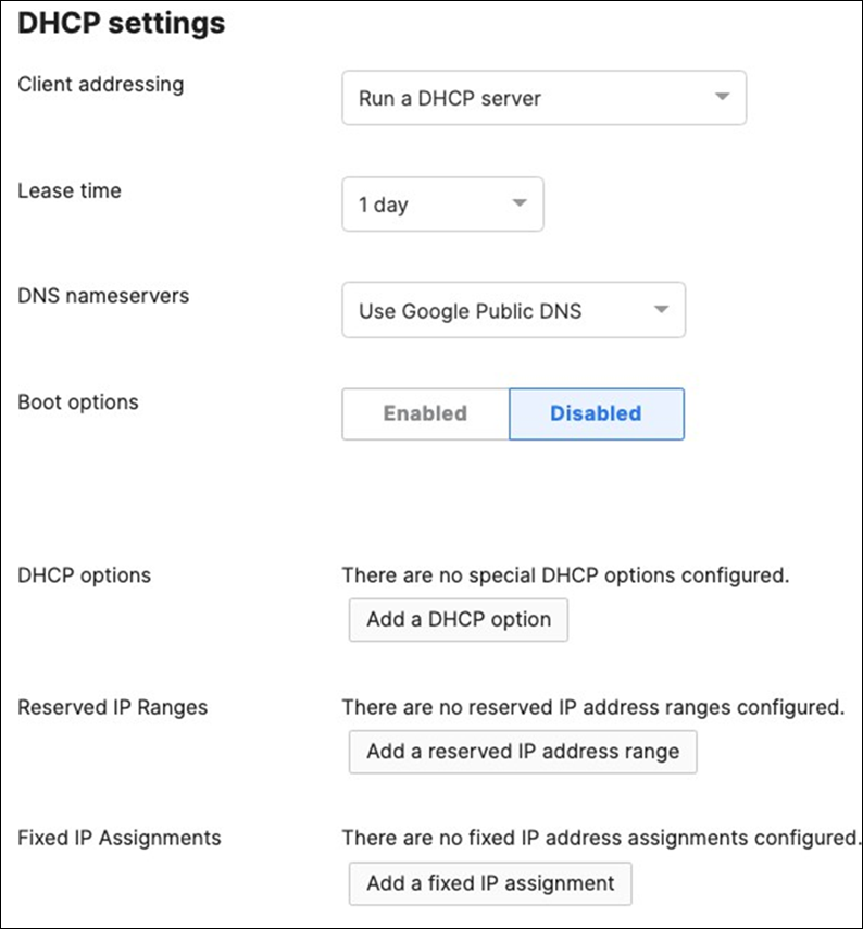
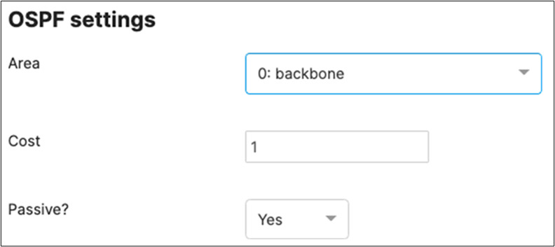
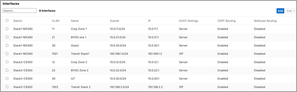
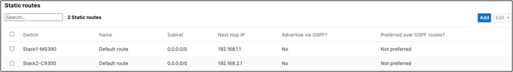
● Please note that the Static Routes shown above are automatically created per stack and they reflect the default gateway settings that you have configured with the first SVI interface created which is in this case the Transit VLAN interface for each Stack
65. Verify that your Core Stack is receiving OSPF routes from its neighbors:
| 9500-01#show ip route Codes: L - local, C - connected, S - static, R - RIP, M - mobile, B - BGP D - EIGRP, EX - EIGRP external, O - OSPF, IA - OSPF inter area N1 - OSPF NSSA external type 1, N2 - OSPF NSSA external type 2 E1 - OSPF external type 1, E2 - OSPF external type 2, m - OMP n - NAT, Ni - NAT inside, No - NAT outside, Nd - NAT DIA i - IS-IS, su - IS-IS summary, L1 - IS-IS level-1, L2 - IS-IS level-2 ia - IS-IS inter area, * - candidate default, U - per-user static route H - NHRP, G - NHRP registered, g - NHRP registration summary o - ODR, P - periodic downloaded static route, l - LISP a - application route + - replicated route, % - next hop override, p - overrides from PfR & - replicated local route overrides by connected
Gateway of last resort is 10.0.200.1 to network 0.0.0.0
S* 0.0.0.0/0 [254/0] via 10.0.200.1 [254/0] via 10.0.100.1 [254/0] via 10.0.3.1 10.0.0.0/8 is variably subnetted, 12 subnets, 2 masks C 10.0.3.0/24 is directly connected, Vlan3 L 10.0.3.2/32 is directly connected, Vlan3 O 10.0.11.0/24 [110/2] via 192.168.1.2, 00:04:13, Vlan1921 O 10.0.12.0/24 [110/2] via 192.168.2.2, 00:03:56, Vlan1922 O 10.0.21.0/24 [110/2] via 192.168.1.2, 00:04:13, Vlan1921 O 10.0.22.0/24 [110/2] via 192.168.2.2, 00:03:56, Vlan1922 O 10.0.30.0/24 [110/2] via 192.168.1.2, 00:04:13, Vlan1921 O 10.0.40.0/24 [110/2] via 192.168.2.2, 00:03:56, Vlan1922 C 10.0.100.0/24 is directly connected, Vlan100 L 10.0.100.2/32 is directly connected, Vlan100 C 10.0.200.0/24 is directly connected, Vlan200 L 10.0.200.2/32 is directly connected, Vlan200 192.168.1.0/24 is variably subnetted, 2 subnets, 2 masks C 192.168.1.0/24 is directly connected, Vlan1921 L 192.168.1.1/32 is directly connected, Vlan1921 192.168.2.0/24 is variably subnetted, 2 subnets, 2 masks C 192.168.2.0/24 is directly connected, Vlan1922 L 192.168.2.1/32 is directly connected, Vlan1922 192.168.3.0/24 is variably subnetted, 2 subnets, 2 masks C 192.168.3.0/24 is directly connected, Vlan1923 L 192.168.3.2/32 is directly connected, Vlan1923 9500-01# |
66. And that concludes the configuration requirements for this design option. Please remember to always click Save at the bottom of the page once you have finished configuring each item on the Meraki Dashboard.
Testing and Verification
Firmware
The following table indicates the firmware versions used in this Campus LAN:
| Device |
Firmware Version |
Notes |
| MX250 WAN Edge |
MX 16.16 |
GA |
| C9500 Core Stack |
|
|
| MS390 Access Stack |
MS 15.14 |
Beta |
| C9300 Access Stack |
MS 15.14 |
Beta |
| MR55 |
28.6.1 |
GA |
| C9166 (MR57) |
28.30 |
Beta |
Device Connectivity
MX WAN Edge
Upstream Connectivity
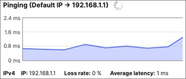
Internet/Cloud Connectivity
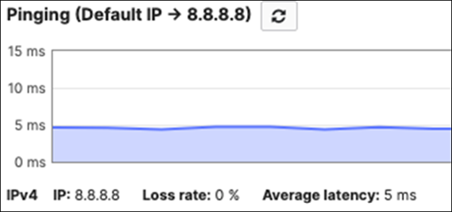
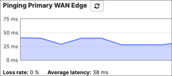
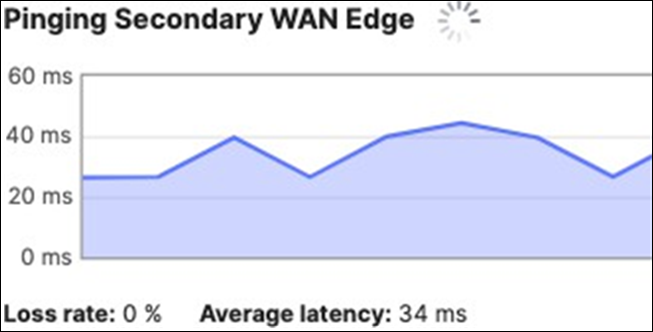
Downstream Connectivity
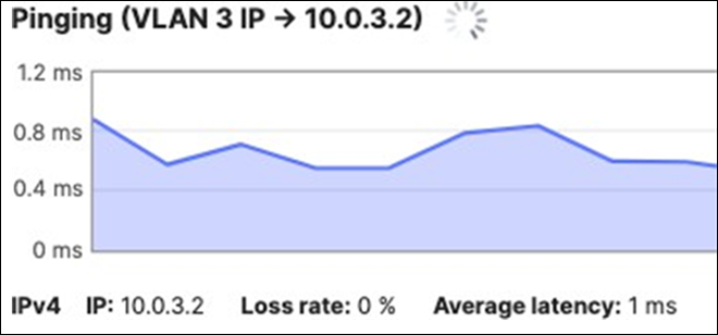
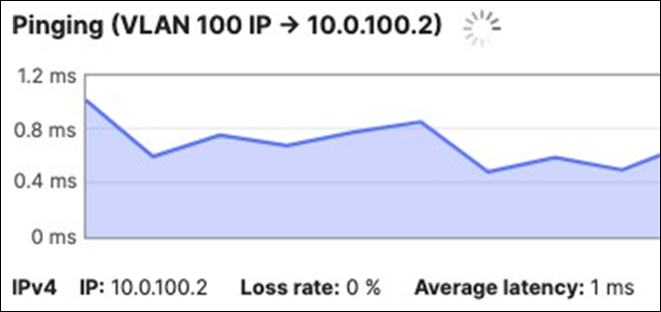
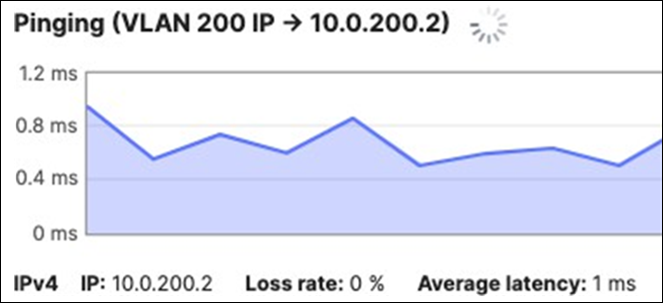
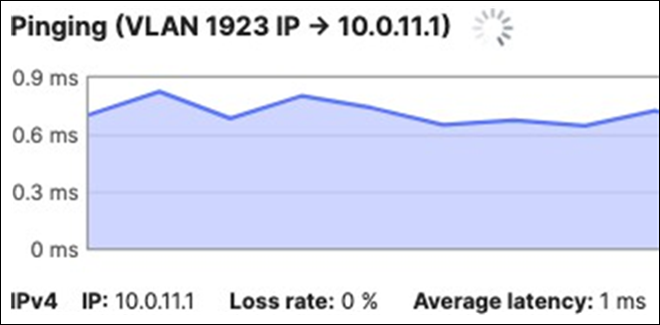
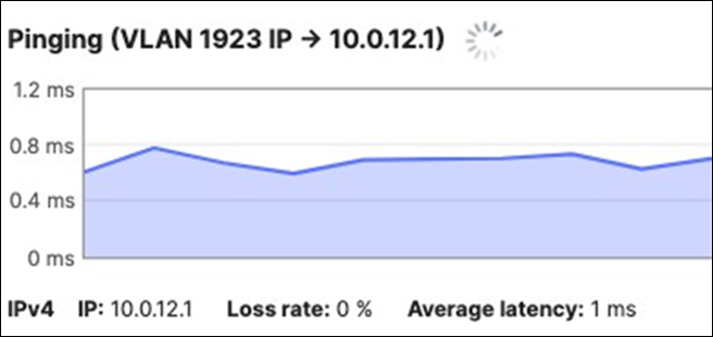
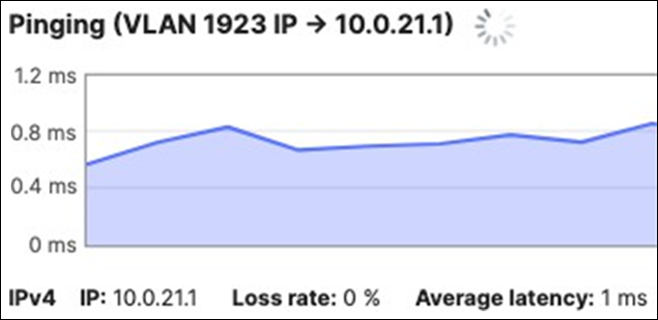
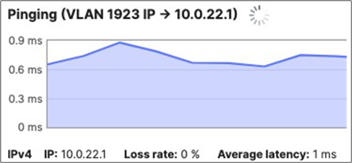
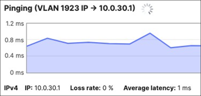
C9500 Core Stack
Upstream Connectivity
| 9500-01#ping 10.0.3.1 Type escape sequence to abort. Sending 5, 100-byte ICMP Echos to 10.0.1.1, timeout is 2 seconds: !!!!! Success rate is 100 percent (5/5), round-trip min/avg/max = 1/1/1 ms 9500-01#ping 192.168.3.1 Type escape sequence to abort. Sending 5, 100-byte ICMP Echos to 192.168.3.1, timeout is 2 seconds: !!!!! Success rate is 100 percent (5/5), round-trip min/avg/max = 1/1/1 ms 9500-01# |
Internet Connectivity
| 9500-01#ping 8.8.8.8 source 192.168.3.2 Type escape sequence to abort. Sending 5, 100-byte ICMP Echos to 8.8.8.8, timeout is 2 seconds: Packet sent with a source address of 192.168.3.2 !!!!! Success rate is 100 percent (5/5), round-trip min/avg/max = 4/4/4 ms 9500-01# 9500-01#ping cisco.com source 192.168.3.2 Type escape sequence to abort. Sending 5, 100-byte ICMP Echos to 72.163.4.185, timeout is 2 seconds: Packet sent with a source address of 192.168.3.2 !!!!! Success rate is 100 percent (5/5), round-trip min/avg/max = 108/108/109 ms 9500-01# |
Downstream Connectivity (Please note that the MS390 and C9300-M platforms will prioritize packet forwarding over ICMP echo replies so it's expected behavior that you might get some drops when you ping the management interface)
| 9500-01#ping 10.0.100.3 Type escape sequence to abort. Sending 5, 100-byte ICMP Echos to 10.0.100.3, timeout is 2 seconds: .!!!! Success rate is 80 percent (4/5), round-trip min/avg/max = 2/2/3 ms 9500-01#ping 10.0.100.4 Type escape sequence to abort. Sending 5, 100-byte ICMP Echos to 10.0.100.4, timeout is 2 seconds: .!!!! Success rate is 80 percent (4/5), round-trip min/avg/max = 2/2/4 ms 9500-01#ping 10.0.200.3 Type escape sequence to abort. Sending 5, 100-byte ICMP Echos to 10.0.200.3, timeout is 2 seconds: !!!!! Success rate is 100 percent (5/5), round-trip min/avg/max = 1/1/1 ms 9500-01#ping 10.0.200.4 Type escape sequence to abort. Sending 5, 100-byte ICMP Echos to 10.0.200.4, timeout is 2 seconds: !!!!! Success rate is 100 percent (5/5), round-trip min/avg/max = 1/1/1 ms 9500-01# |
In case of connectivity issues, please check the following:
| Item |
Expected Configuration/ Status |
Verification |
Actual Configuration |
|
| C9500 Uplinks to MX Edge: |
Trunk , VLAN 3 |
sh ip int brief |
!all uplinks! |
|
| TwentyFiveGigE1/0/1 |
DAI Trusted |
sh run int <interface> |
switchport mode access |
|
| TwentyFiveGigE1/0/2 |
up/up |
sh spanning-tree int <interface> |
ip arp inspection trust |
|
| TwentyFiveGigE2/0/1 |
|
|
ip dhcp snooping trust |
|
| TwentyFiveGigE2/0/2 |
|
|
End ! |
|
| STP interface Configuration: |
STP Configuration |
sh run int <interface> |
!where applicable! |
|
| TwentyFiveGigE1/0/1 |
N/A |
|
udld port aggressive |
|
| TwentyFiveGigE1/0/2 |
N/A |
|
spanning-tree guard root |
|
| TwentyFiveGigE2/0/1 |
N/A |
|
end |
|
| TwentyFiveGigE2/0/2 |
N/A |
|
! |
|
| TwentyFiveGigE1/0/23 |
Root Guard + UDLD aggressive |
|
|
|
| TwentyFiveGigE1/0/24 |
Root Guard + UDLD aggressive |
|
|
|
| TwentyFiveGigE2/0/23 |
Root Guard + UDLD aggressive |
|
|
|
| TwentyFiveGigE2/0/24 |
Root Guard + UDLD aggressive |
|
|
|
| STP interface Status: |
STP status: |
sh spanning-tree int <interface> |
!only PHY interfaces! |
|
| TwentyFiveGigE1/0/1 |
FWD |
|
spanning-tree mode mst |
|
| TwentyFiveGigE1/0/2 |
BLK |
|
spanning-tree extend system-id |
|
| TwentyFiveGigE2/0/1 |
FWD |
|
! |
|
| TwentyFiveGigE2/0/2 |
BLK |
|
spanning-tree mst configuration |
|
| Po1 |
FWD |
|
name region1 |
|
| Po2 |
FWD |
|
revision 1 ! |
|
|
|
|
|
spanning-tree mst 0 priority 4096 |
|
| Default Route |
DHCP, VLAN 1923 |
sh int vlan1923 hip route |
! interface Vlan1923 ip address 192.168.3.2 255.255.255.0 end ! sh ip route | in /0 S* 0.0.0.0/0 [254/0] via 192.168.3.1 |
|
| MX WAN Edge Downlinks: |
Trunk , VLAN 3 |
Navigate to Security and SD-WAN > Configure > Addressing and VLANs |
|
|
| Port 19 |
|
|
|
|
| Port 20 |
|
|
|
|
| C9500 Downlinks: |
Trunk |
sh run int |
!PHY 23! |
|
|
|
DAI Trusted |
switchport trunk allowed vlan 100,1921 |
||
|
|
SGT 2 Trusted |
switchport mode trunk |
||
|
|
No CTS enforcement |
ip arp inspection trust |
||
| TwentyFiveGigE1/0/23 |
VLAN 100 / 100, 1921 |
!PHY 24! |
||
| TwentyFiveGigE1/0/24 |
VLAN 200 / 200, 1922 |
switchport trunk allowed vlan 200,1922 |
||
| TwentyFiveGigE2/0/23 |
VLN 100 / 100, 1921 |
switchport mode trunk |
||
| TwentyFiveGigE2/0/24 |
VLAN 200 / 200, 1922 |
ip arp inspection trust !BOTH! cts manual policy static sgt 2 trusted no cts role-based enforcement ! end |
||
|
|
|
|||
| C9500 Ether-Channels: |
|
|
!PHY 23! |
|
| TwentyFiveGigE1/0/23 |
Channel-Group 1 |
sh run int <interface> |
channel-group 1 mode active |
|
| TwentyFiveGigE1/0/24 |
Channel-Group 2 |
sh etherchannel <#> sum |
!PHY 24! |
|
| TwentyFiveGigE2/0/23 |
Channel-Group 1 |
sh ip int brief | in Po |
channel-group 2 mode active |
|
| TwentyFiveGigE2/0/24 |
Channel-Group 2 |
|
! |
|
| Po1 |
up/up |
|
end |
|
| Po2 |
up/up |
|
|
|
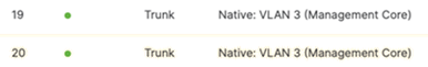
MS390 Access Stack
Upstream Connectivity
| Tech Tip: Please note that the MS390 and C9300 switches use a separate routing table for management traffic than the configured SVIs. As such, you won't be able to verify connectivity using ping tool from the switch page to its default gateway (e.g. 10.0.100.1) since we have not created a L3 interface for the Management VLAN (e.g. VLAN 100). Upstream connectivity verification should be done using one of the SVI interfaces configured on the stack/ switch to the upstream Transit VLAN configured on the Edge MX appliance. (e.g. VLAN 1923) |
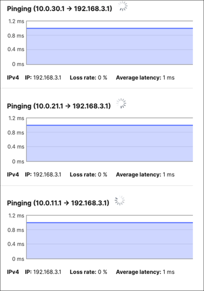
Internet/Cloud Connectivity
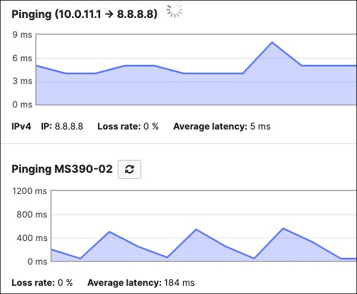
Downstream Connectivity
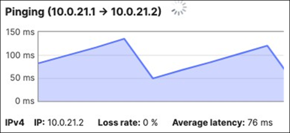
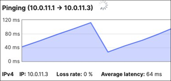
C9300 Access Stack
Upstream Connectivity
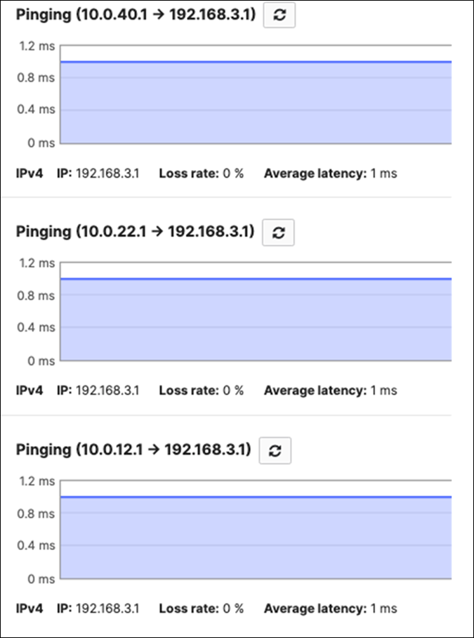
Internet/Cloud Connectivity
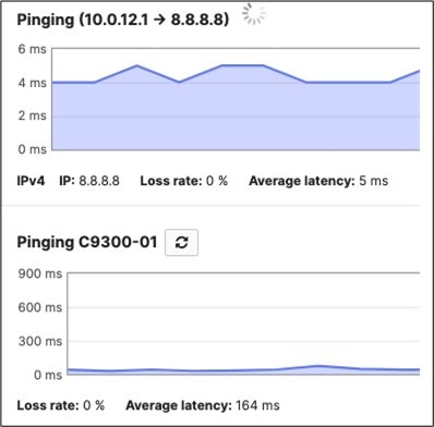
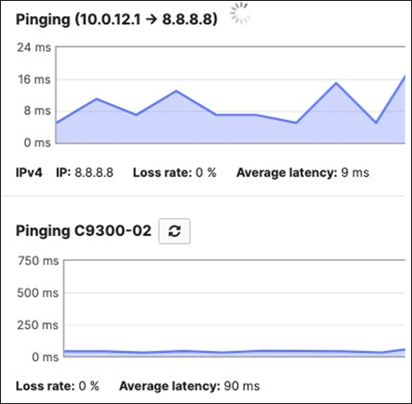
Downstream Connectivity
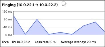
MR Access Points
Downstream Connectivity
Client Connectivity
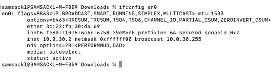
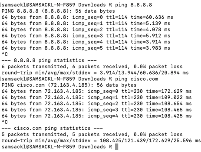
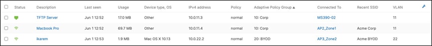
802.1x Authentication
802.1x authentication has been tested on both Corp and BYOD SSIDs. Dashboard will be checked to verify the correct IP address assignment and username. Packet captures will also be checked to verify the correct SGT assignment. In the final section, ISE logs will show the authentication status and authorization policy applied.
| Client |
SSID/Port |
Username |
VLAN |
SGT |
| iKarem f4:5c:89:b9:35:09 10.0.22.2 |
Acme BYOD |
byod1 |
22 |
20 |
| iPhone 11 12:99:2a:2d:d5:d6 10.0.30.2 |
Guest |
N/A |
30 |
30 |
| MacBook Pro 8c:ae:4c:dd:15:19 10.0.11.3 |
MS390-02 Port 4 |
Corp1 |
10 |
10 |
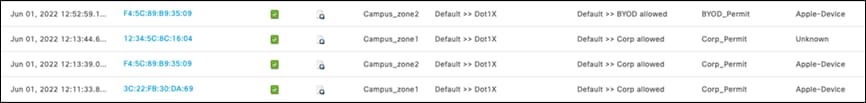
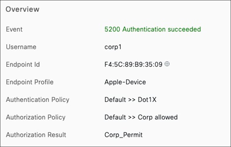
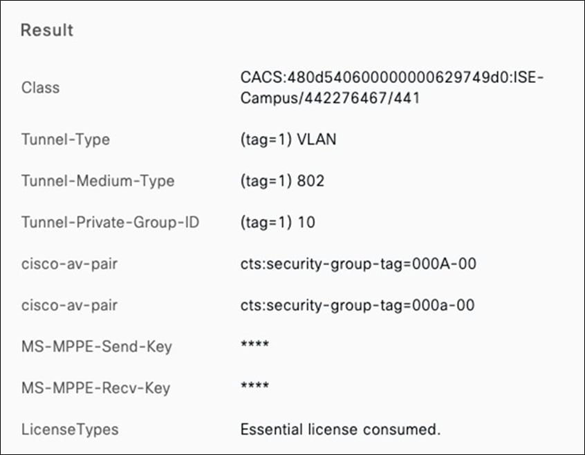
| Tech Tip: Please note that the configuration of the Cisco ISE is out of scope of this CVD. Please refer to Cisco ISE administration guide for details on configuring policy sets on Cisco ISE. Also, please refer to this article for more information on configuring Cisco ISE with Cisco Meraki Devices |
VLAN Assignment
This section will validate that VLANs are assigned correctly based on the VLAN tag. The following client was used to test the connectivity in the designated VLAN:
|
|
Acme Corp |
Acme BYOD |
||
| AP |
AP2_Zone1 |
AP3_Zone2 |
AP2_Zone1 |
AP3_Zone2 |
| Expected VLAN |
11 |
12 |
21 |
22 |
| Testing Client |
12:34:5C:8C:16:0 |
12:34:5C:8C:16:0 |
46:F2:0C:4B:E7:FD |
46:F2:0C:4B:E7:FD |
| Assigned IP Address / VLAN |
10.0.11.3 / VLAN 11 |
10.0.12.3 / VLAN 12 |
10.0.21.3 / VLAN 21 |
10.0.22.2 / VLAN 22 |
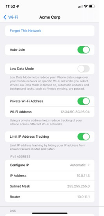
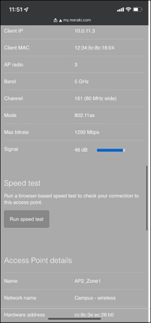
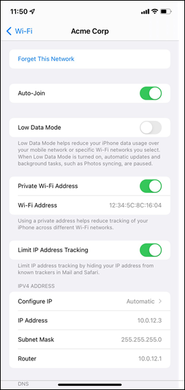
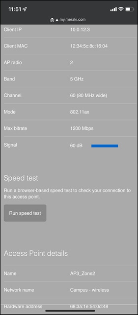
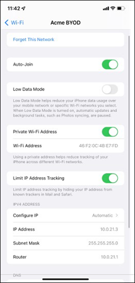
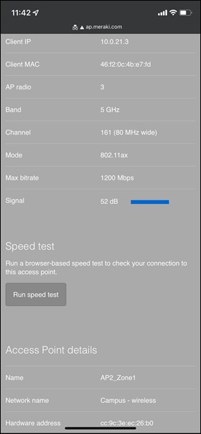
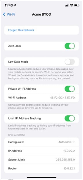
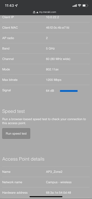
STP Convergence
STP convergence will be tested using several methods as outlined below. Please see the following table for steady-state of the Campus LAN before testing:
|
|
|
Bridge ID |
STP Status |
| C9500-01 |
Master |
4096:b0c5.3c60.fba0 |
|
| C9500-02 |
Member |
4096.40b5.c111.01e0 |
|
| MS390-01 |
Master |
61440:2c3f.0b04.7e80 |
STP ROOT b0:c5:3c:60:fb:a0 (priority 4096) |
| MS390-02 |
Member |
61440:2c3f.0b0f.ec00 |
Blocking ports None |
| C9300-01 |
Master |
61440:a4b4.395f.2a8b |
STP ROOT b0:c5:3c:60:fb:a0 (priority 4096) |
| C9300-02 |
Member |
61440:4ce1.75b0.ba00 |
Blocking ports None |
| Client Device |
|
IP Address: 10.0.20.4 |
|
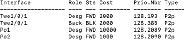
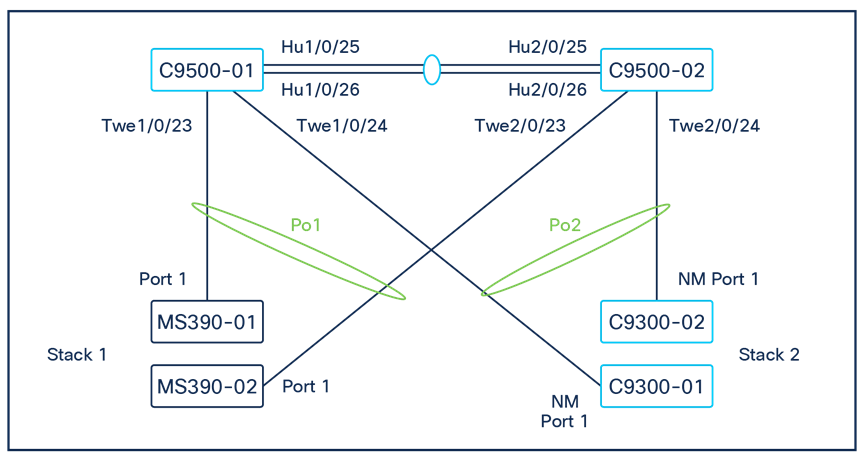
Introducing loops (Access to Core)
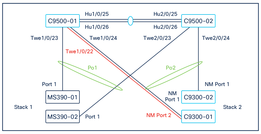
A loop was introduced by adding a link between C9300-01 /NM Port 2 and C9500 Core Stack / Port TwentyFiveGigE1/0/22 (Please note that for the purposes of this test, the interface has been unshut and configured as a Trunk port with Native VLAN 1 with STP guards on that interface)
| 9500-01#show ip interface brief | in TwentyFiveGigE1/0/22 TwentyFiveGigE1/0/22 unassigned YES unset up up ow9500-01#show run interface TwentyFiveGigE1/0/22 Building configuration...
Current configuration : 132 bytes ! interface TwentyFiveGigE1/0/22 switchport trunk native vlan 200 switchport trunk allowed vlan 200,1922 switchport mode trunk spanning-tree guard root end
9500-01# 9500-01#show spanning-tree
MST0 Spanning tree enabled protocol mstp Root ID Priority 4096 Address b0c5.3c60.fba0 This bridge is the root Hello Time 2 sec Max Age 20 sec Forward Delay 15 sec
Bridge ID Priority 4096 (priority 4096 sys-id-ext 0) Address b0c5.3c60.fba0 Hello Time 2 sec Max Age 20 sec Forward Delay 15 sec Interface Role Sts Cost Prio.Nbr Type ------------------------------------------------------- Twe1/0/1 Desg FWD 2000 128.193 P2p Twe1/0/2 Desg FWD 2000 128.194 P2p Twe1/0/22 Desg FWD 2000 128.214 P2p Twe2/0/1 Back BLK 2000 128.385 P2p Twe2/0/2 Back BLK 2000 128.386 P2p Po1 Desg FWD 10000 128.2089 P2p Po2 Desg FWD 1000 128.2090 P2p |
Interface Twe1/0/22 is in STP FWD state (As expected since this is the Root bridge)
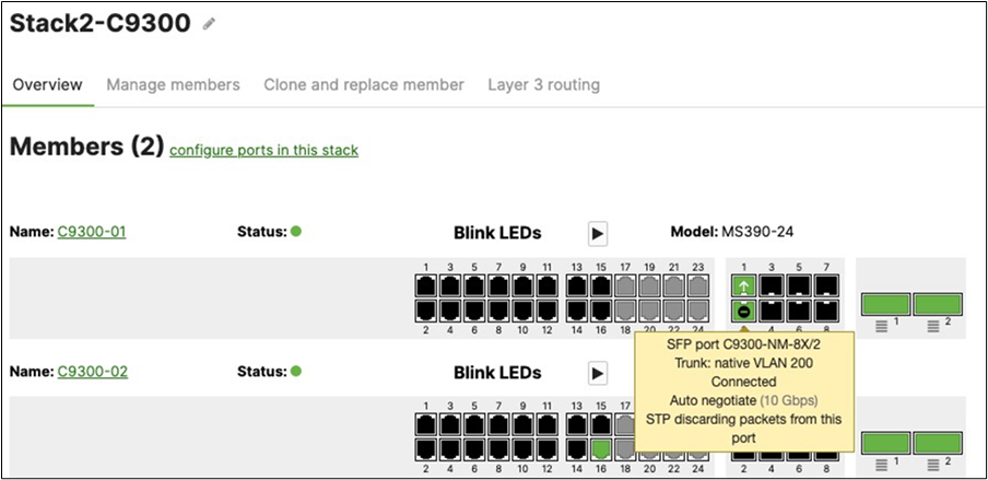
Interface 26 is in STP BLK state (As expected since the Ether-channel is in FWD state)
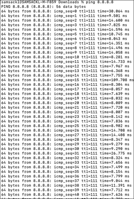
| Note: No impact on traffic flow for wireless and wired clients |
Introducing Loops (Access Layer, with STP Guard: Loop Guard)
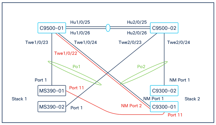
For the purposes of this test and in addition to the previous loop connections, the following ports were connected: MS390-01 / Port 11 < - > C9300-01 / Port 11
Please note that the port configuration for both ports was changed to assign a common VLAN (in this case VLAN 99). Please see the following configuration that has been applied to both ports:
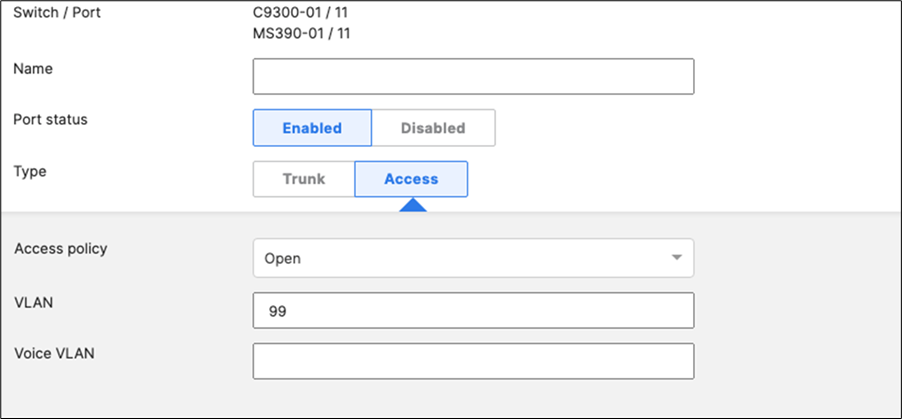
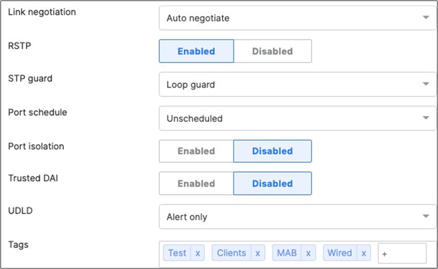
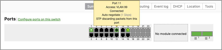
| Note: Port 11 on MS390-01 in STP BLK state (Bridge ID: 61440:2c3f.0b04.7e80) |
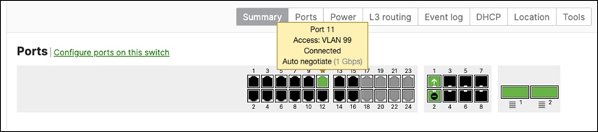
| Note: Port 11 on C9300-01 in STP FWD state (Bridge ID: 61440:a4b4.395f.2a8b) |
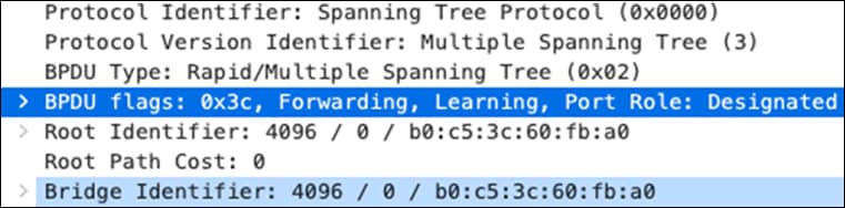
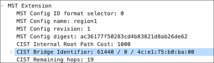
| Note: Packet capture on MS390-01 / Port 11 shows that Bridge ID: 61440:4ce1.75b0.ba00 is relaying the Root bridge BPDUs with Root Bridge ID: 4096:b0c5.3c60.fba0 |
Introducing Loops (Access Layer, without STP Guard)
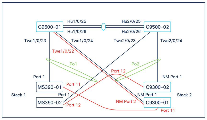
For the purposes of this test and in addition to the previous loop connections, the following ports were connected: MS390-02 / Port 12 < - > C9300-02 / Port 12.
Please note that the port configuration for both ports was changed to assign a common VLAN (in this case VLAN 99). Please see the following configuration that has been applied to both ports:
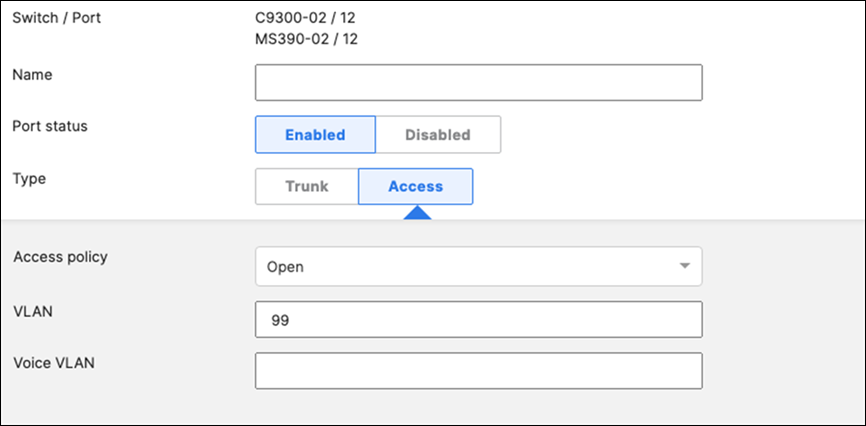
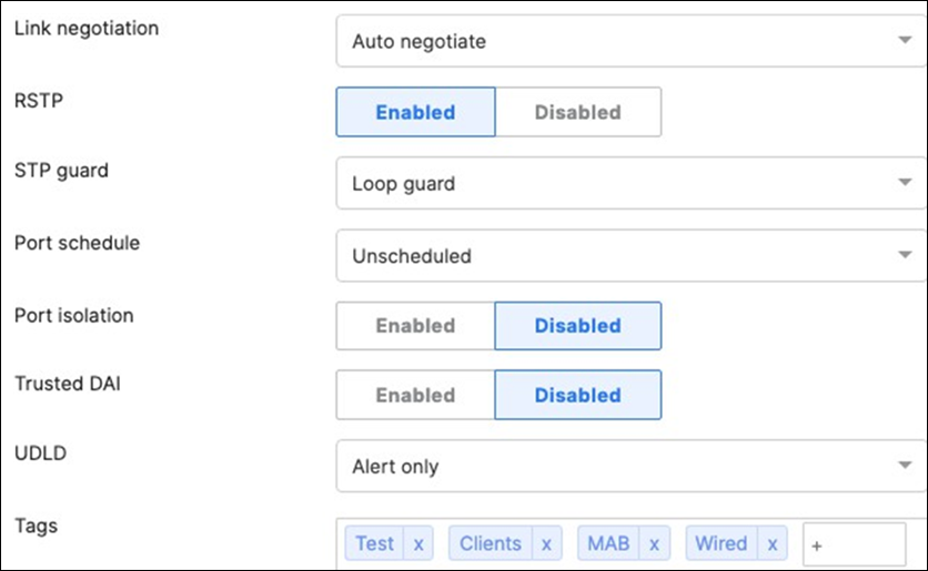

| Note: MS390-02 / Port 12 is in STP BLK state (Bridge ID: 61440:2c3f.0b0f.ec00) |
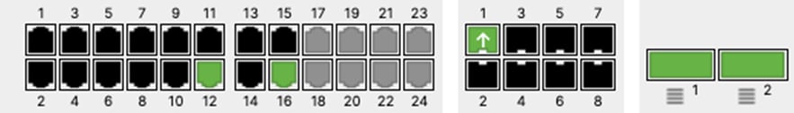
| Note: C9300-02 / Port 12 is in STP FWD state (Bridge ID: 61440:4ce1.75b0.ba00) |
Introducing Loops (Core Layer)
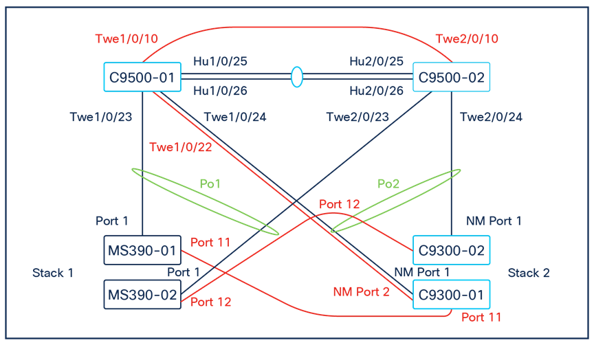
For the purpose of this test and in addition to the previous loop connections, the following ports were connected:
Port Twe1/0/10 to port Twe2/0/10 on the C9500 Core switches.
| 9500-01#show run interface Twe1/0/10 Building configuration...
Current configuration : 132 bytes ! interface TwentyFiveGigE1/0/10 switchport trunk native vlan 3 switchport trunk allowed vlan 3,100,200,1921,1922,1923 switchport mode trunk spanning-tree guard loop end
9500-01#show run interface Twe2/0/10 Building configuration...
Current configuration : 132 bytes ! interface TwentyFiveGigE2/0/10 switchport trunk native vlan 3 switchport trunk allowed vlan 3,100,200,1921,1922,1923 switchport mode trunk spanning-tree guard loop end
9500-01# 9500-01#show ip interface brief | in TwentyFiveGigE1/0/10 TwentyFiveGigE1/0/10 unassigned YES unset up up 9500-01# 9500-01#show ip interface brief | in TwentyFiveGigE2/0/10 TwentyFiveGigE2/0/10 unassigned YES unset up up 9500-01#show spanning-tree
MST0 Spanning tree enabled protocol mstp Root ID Priority 4096 Address b0c5.3c60.fba0 This bridge is the root Hello Time 2 sec Max Age 20 sec Forward Delay 15 sec Bridge ID Priority 4096 (priority 4096 sys-id-ext 0) Address b0c5.3c60.fba0 Hello Time 2 sec Max Age 20 sec Forward Delay 15 sec Interface Role Sts Cost Prio.Nbr Type -------------------------------------------- Twe1/0/1 Desg FWD 2000 128.193 P2p Twe1/0/2 Desg FWD 2000 128.194 P2p Twe1/0/10 Desg FWD 2000 128.202 P2p Twe1/0/22 Desg FWD 2000 128.214 P2p Twe2/0/1 Back BLK 2000 128.385 P2p Twe2/0/2 Back BLK 2000 128.386 P2p Twe2/0/10 Back BLK 2000 128.394 P2p Po1 Desg FWD 10000 128.2089 P2p Po2 Desg FWD 1000 128.2090 P2p
9500-01#show spanning-tree interface Twe2/0/10 detail Port 394 (TwentyFiveGigE2/0/10) of MST0 is backup blocking Port path cost 2000, Port priority 128, Port Identifier 128.394. Designated root has priority 4096, address b0c5.3c60.fba0 Designated bridge has priority 4096, address b0c5.3c60.fba0 Designated port id is 128.202, designated path cost 0 Timers: message age 4, forward delay 0, hold 0 Number of transitions to forwarding state: 0 Link type is point-to-point by default, Internal PVST Simulation is enabled by default Loop guard is enabled on the port BPDU: sent 2, received 66 9500-01# |
Introducing Rogue Bridge in VLAN 200
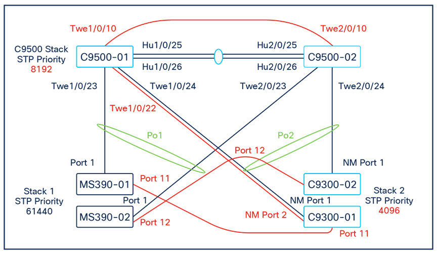
For the purpose of this test and in addition to the previous loop connections, the Bridge priority on C9300 Stack will be reduced to 4096 (likely root) and increasing the Bridge priority on C9500 to 8192.
● Downlinks on C9500 are configured with STP Root Guard
● Access Layer Links (Stack to Stack) are configured with STP Loop Guard + UDLD
| 9500-01(config)#spanning-tree mst 0 priority 8192 9500-01(config)#end 9500-01#show spanning-tree MST0 Spanning tree enabled protocol mstp Root ID Priority 8192 Address b0c5.3c60.fba0 This bridge is the root Hello Time 2 sec Max Age 20 sec Forward Delay 15 sec Bridge ID Priority 8192 (priority 8192 sys-id-ext 0) Address b0c5.3c60.fba0 Hello Time 2 sec Max Age 20 sec Forward Delay 15 sec Interface Role StsCost Prio.Nbr Type ----------------------------------------------------- Twe1/0/1 Desg FWD 2000 128.193 P2p Twe1/0/2 Desg FWD 2000 128.194 P2p Twe1/0/10 Desg FWD 2000 128.202 P2p Twe1/0/22 Desg BKN*2000 128.214 P2p *ROOT_Inc Twe2/0/1 Back BLK 2000 128.385 P2p Twe2/0/2 Back BLK 2000 128.386 P2p Twe2/0/10 Back BLK 2000 128.394 P2p Po1 Desg BKN*10000 128.2089 P2p *ROOT_Inc Po2 Desg BKN*1000 128.2090 P2p *ROOT_Inc
9500-01# |
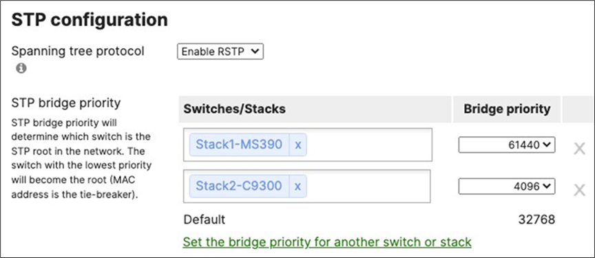
| 9500-01#show spanning-tree MST0 Spanning tree enabled protocol mstp Root ID Priority 8192 Address b0c5.3c60.fba0 This bridge is the root Hello Time 2 sec Max Age 20 sec Forward Delay 15 sec Bridge ID Priority 8192 (priority 8192 sys-id-ext 0) Address b0c5.3c60.fba0 Hello Time 2 sec Max Age 20 sec Forward Delay 15 sec Interface Role Sts Cost Prio.Nbr Type --------------------------------------------- 9500-01#sh spanning-tree MST0 Spanning tree enabled protocol mstp Root ID Priority 8192 Address b0c5.3c60.fba0 This bridge is the root Hello Time 2 sec Max Age 20 sec Forward Delay 15 sec
Bridge ID Priority 8192 (priority 8192 sys-id-ext 0) Address b0c5.3c60.fba0 Hello Time 2 sec Max Age 20 sec Forward Delay 15 sec Interface Role StsCost Prio.Nbr Type ----------------------------------------------------- Twe1/0/1 Desg FWD 2000 128.193 P2p Twe1/0/2 Desg FWD 2000 128.194 P2p Twe1/0/10 Desg FWD 2000 128.202 P2p Twe1/0/22 Desg BKN*2000 128.214 P2p *ROOT_Inc Twe2/0/1 Back BLK 2000 128.385 P2p Twe2/0/2 Back BLK 2000 128.386 P2p Twe2/0/10 Back BLK 2000 128.394 P2p Po1 Desg BKN*10000 128.2089 P2p *ROOT_Inc Po2 Desg BKN*1000 128.2090 P2p *ROOT_Inc
9500-01# 9500-01#show spanning-tree interface Po1 detail Port 2089 (Port-channel1) of MST0 is broken (Root Inconsistent) Port path cost 10000, Port priority 128, Port Identifier 128.2089. Designated root has priority 8192, address b0c5.3c60.fba0 Designated bridge has priority 8192, address b0c5.3c60.fba0 Designated port id is 128.2089, designated path cost 0 Timers: message age 5, forward delay 0, hold 0 Number of transitions to forwarding state: 1 Link type is point-to-point by default, Internal PVST Simulation is enabled by default Root guard is enabled on the port BPDU: sent 15929, received 1230
9500-01#show spanning-tree interface Po2 detail Port 2090 (Port-channel2) of MST0 is broken (Root Inconsistent) Port path cost 1000, Port priority 128, Port Identifier 128.2090. Designated root has priority 8192, address b0c5.3c60.fba0 Designated bridge has priority 8192, address b0c5.3c60.fba0 Designated port id is 128.2090, designated path cost 0 Timers: message age 5, forward delay 0, hold 0 Number of transitions to forwarding state: 1 Link type is point-to-point by default, Internal PVST Simulation is enabled by default Root guard is enabled on the port BPDU: sent 15849, received 1330 9500-01# |
C9500 Core Stack is still the Root Bridge (i.e. The root Bridge placement has been enforced).
Downlinks to C9300 and MS390 stacks are in STP Root Inconsistent State which caused all access switches to go offline on Dashboard.
| Note: Please note that this caused client disruption, and no traffic was passing since the C9500 Core Stack put all downlink ports into Root inconsistent state. |
To recover access switches, you will need to change the STP priority on the C9500 Core stack to 0 which ensures that your core stack becomes the root of the CIST. Alternatively, you can configure STP root Guard on the MS390 ports facing the C9300 and thus the MS390s will come back online.
The reason why all access switches went online on dashboard is that the C9300 was the root for the access layer (priority 4096) and thus the MS390s were passing traffic to Dashboard via the C9300s. Configuring STP Root Guard on the ports facing C9300 recovered the MS390s and client connectivity.
On the other hand, changing the STP priority on the C9500 core stack pulled back the Root to the core layer and recovered all switches on the access layer.
| Tech Tip: It is considered best practices to avoid assigning STP priority on your network to 0 on any device which gives you room for adding devices in the future and for maintenance purposes. In this instance, configuring STP priority 0 allowed us to recover the network which wouldn't have been possible if priority 0 was configured already on the network. Having said that, please remember to revert the STP priority on your C9500 Core Stack after recovering the network. (Default value 4096) |
| 9500-01(config)#spanning-tree mst 0 priority 0 9500-01(config)# 9500-01(config)#end 9500-01#show spanning-tree MST0 Spanning tree enabled protocol mstp Root ID Priority 0 Address b0c5.3c60.fba0 This bridge is the root Hello Time 2 sec Max Age 20 sec Forward Delay 15 sec Bridge ID Priority 0 (priority 0 sys-id-ext 0) Address b0c5.3c60.fba0 Hello Time 2 sec Max Age 20 sec Forward Delay 15 sec Interface Role Sts Cost Prio.Nbr Type --------------------------------------------- Twe1/0/1 Desg FWD 2000 128.193 P2p Twe1/0/2 Desg FWD 2000 128.194 P2p Twe1/0/10 Desg FWD 2000 128.202 P2p Twe1/0/22 Desg FWD 2000 128.214 P2p Twe2/0/1 Back BLK 2000 128.385 P2p Twe2/0/2 Back BLK 2000 128.386 P2p Twe2/0/10 Back BLK 2000 128.394 P2p Po1 Desg FWD 10000 128.2089 P2p Po2 Desg FWD 1000 128.2090 P2p 9500-01#ping 10.0.200.3 Type escape sequence to abort. Sending 5, 100-byte ICMP Echos to 10.0.200.3, timeout is 2 seconds: !!!!! Success rate is 100 percent (5/5), round-trip min/avg/max = 2/2/3 ms 9500-01#ping 10.0.100.3 Type escape sequence to abort. Sending 5, 100-byte ICMP Echos to 10.0.100.3, timeout is 2 seconds: .!!!! Success rate is 80 percent (4/5), round-trip min/avg/max = 2/2/3 ms 9500-01# |
Reverting all configurations back to its original state:
1. Disconnect and shutdown interface TwentyFiveGigE1/0/22
2. Disconnect port 11 on MS390-01 and C9300-01 and remove Loop Guard and UDLD
3. Disconnect port 12 on MS390-02 and C9300-02
4. Disconnect and revert port TwentyFiveGigE1/0/10 and TwentyFiveGigE20/10 back to access with VLAN 1 and shutdown
5. Change MST priority on C9300 stack to 61440
6. Change MST priority on C9500 Core Stack to 4096
High Availability and Failover
Here's the steady-state physical architecture for reference:
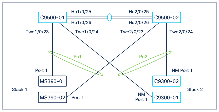
MX WAN Edge Failover

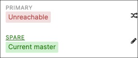
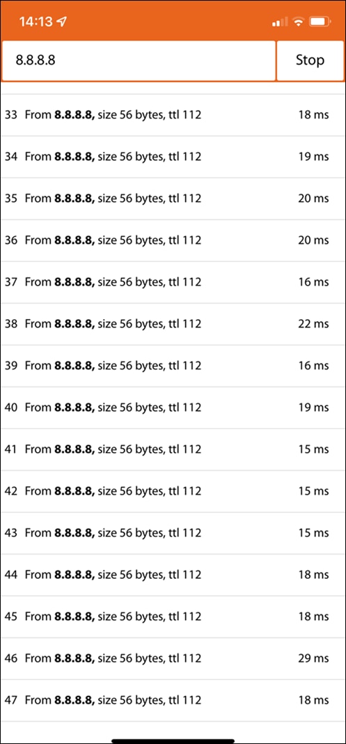
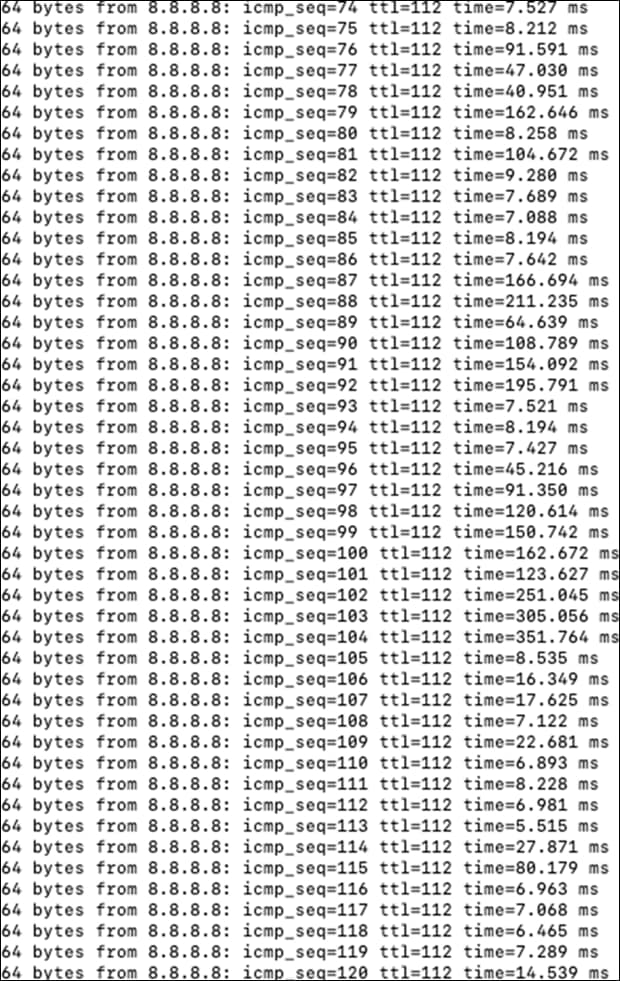
| Note: Client traffic was not disrupted during failover event for both Wireless and Wired clients. |
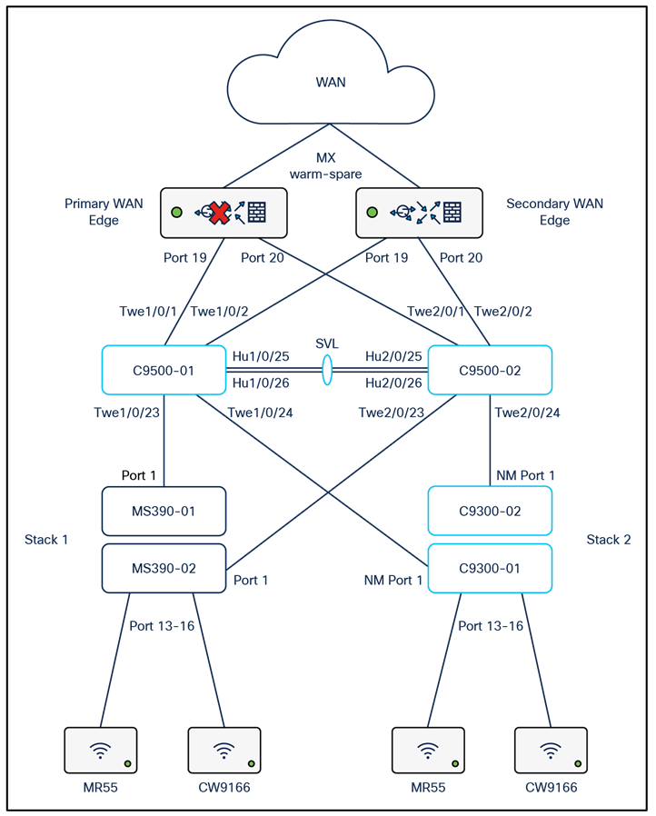
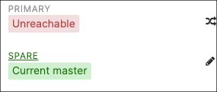
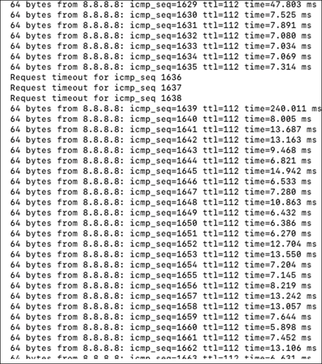
| Note: Client traffic disrupted for about 1-3 secs |
C9500 Core Stack Loss of Uplink
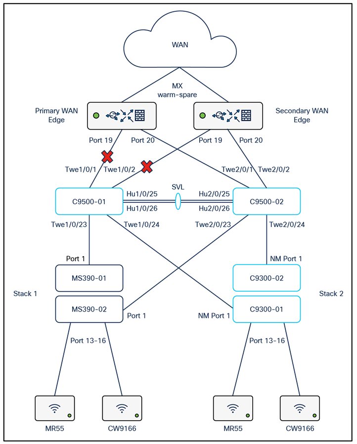
For the purpose of this test, ports TwentyFiveGigE1/0/1 and TwentyFiveGigE1/0/2 will be disconnected.
| 9500-01#show ip interface brief TwentyFiveGigE1/0/1 unassigned YES unset down down TwentyFiveGigE1/0/2 unassigned YES unset down down TwentyFiveGigE2/0/1 unassigned YES unset up up TwentyFiveGigE2/0/2 unassigned YES unset up up 9500-01#show switch Switch/Stack Mac Address : b0c5.3c60.fba0 - Local Mac Address Mac persistency wait time: Indefinite H/W Current ---------------------------------------------------------- Switch# Role Mac Address Priority Version State *1 Active b0c5.3c60.fba0 5 V02 Ready 2 Standby 40b5.c111.01e0 1 V02 Ready 9500-01# |
| Note: Wireless client traffic flow disrupted for about 30 secs |
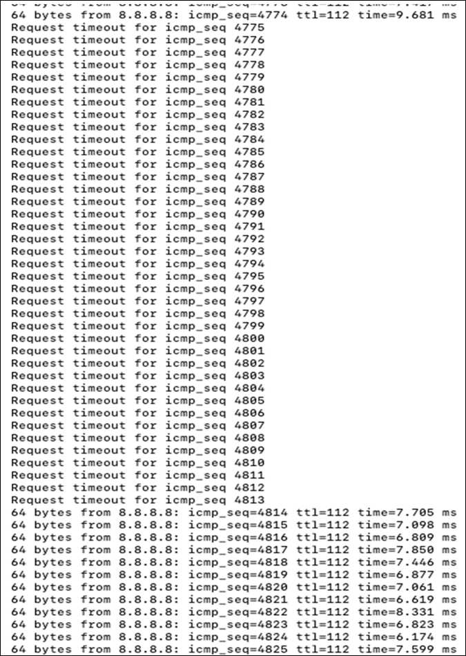
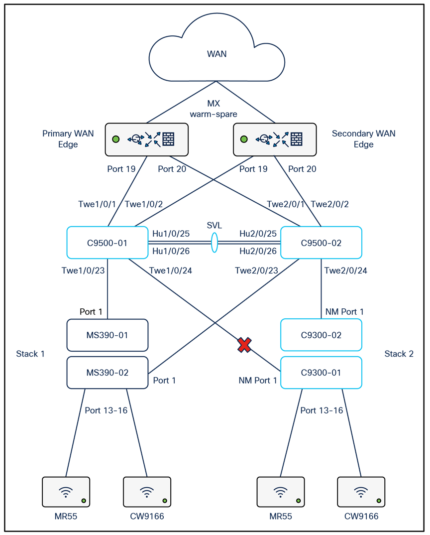
For the purpose of this test, NM Port 1 on C9300-01 (Master switch) will be disconnected.
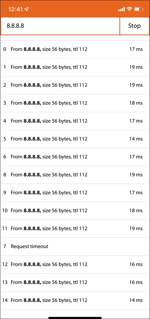
| Note: Wireless client traffic flow disrupted for about 1 sec |
MS390 Stack Loss of Uplink
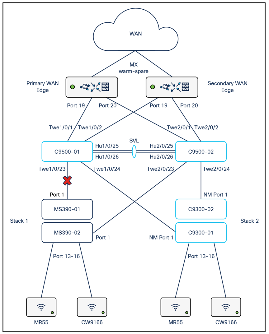
For the purpose of this test, port 1 on MS390-01 (Master switch) will be disconnected.
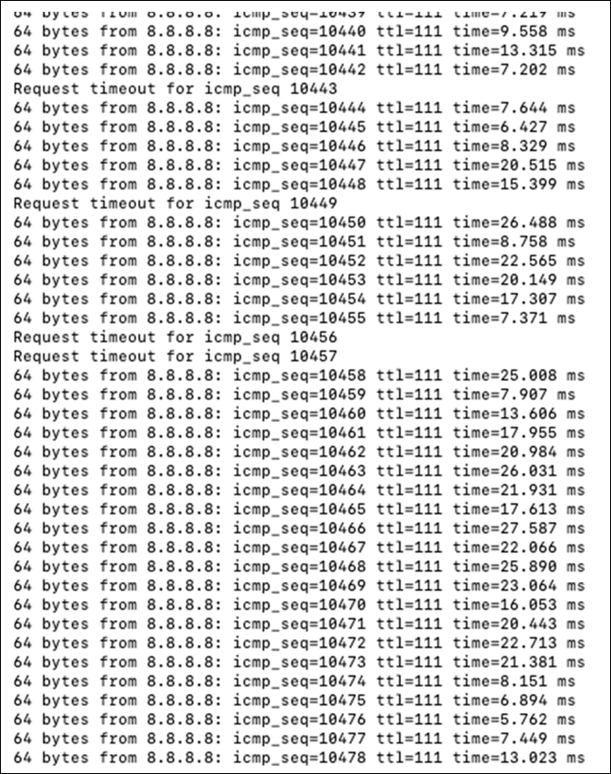
| Note: Wireless client traffic flow disrupted for about 2 secs |
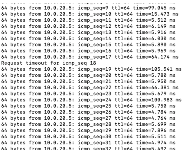
| Note: Wireless client traffic on Campus LAN disrupted for about 1 sec |
QoS
For the purpose of this test, packet capture will be taken between two clients running a Webex session. Packet capture will be taken on the Edge (i.e. MR wireless and wired interfaces) then on the Access (i.e. the MS390 or C9300 uplink port) then on the MX WAN Downlink and finally on the MX WAN Uplink. The table below shows the testing components and the expected QoS behavior:
| Client |
Application |
Access Point (Wired) Expected QoS |
Access Switch Uplink Port Expected QoS |
MX Appliance Uplink Port Expected QoS |
| Client #1 (10.0.20.2) iPhone 11 (cc:66:0a:3e:44:69) |
Webex (UDP 9000) |
AP3_Zone2 / AF41 / DSCP 34 |
C9300-02 (Port 25) / AF41 / DSCP 34 |
AF41 / DSCP 34 |
| iTunes |
AP3_Zone2 / AF21 / DSCP 18 |
C9300-02 (Port 25) / AF21 / DSCP 18 |
AF21 / DSCP 18 |
|
| Client #2 (10.0.20.3) MacBook Pro (3c:22:fb:30:da:69) |
Webex (UDP 9000) |
AP2_Zone1 / AF41 / DSCP 34 |
MS390-01 (Port 1) / AF41 / DSCP 34 |
AF41 / DSCP 34 |
| Dropbox |
AP2_Zone1 / AF0 / DSCP 0 |
MS390-01 (Port 1) / AF0 / DSCP 0 |
AF0 / DSCP 0 |
Access Point Wired Port pcaps
Client #1
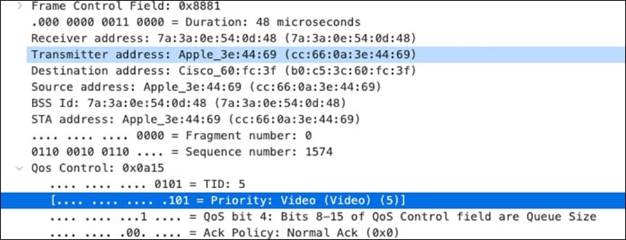
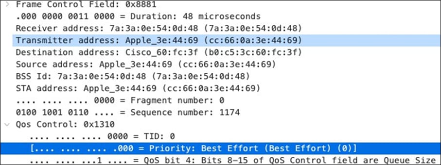
Client #2
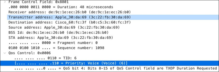
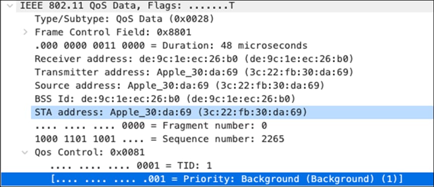
Access Point Wired Port pcaps
Client #1
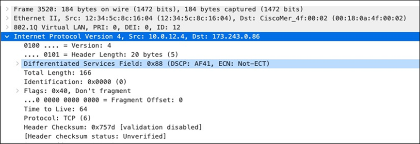
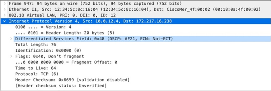
Client #2
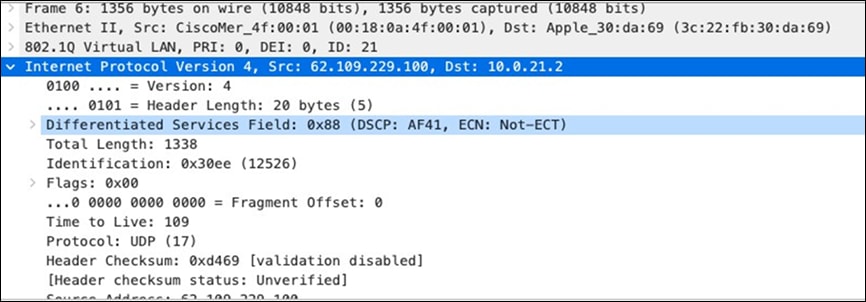
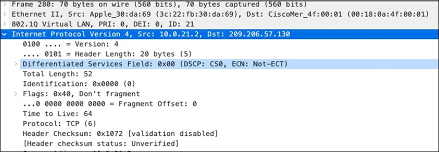
Access Switch Uplink pcaps
Client #1
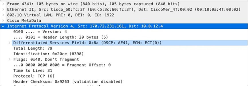
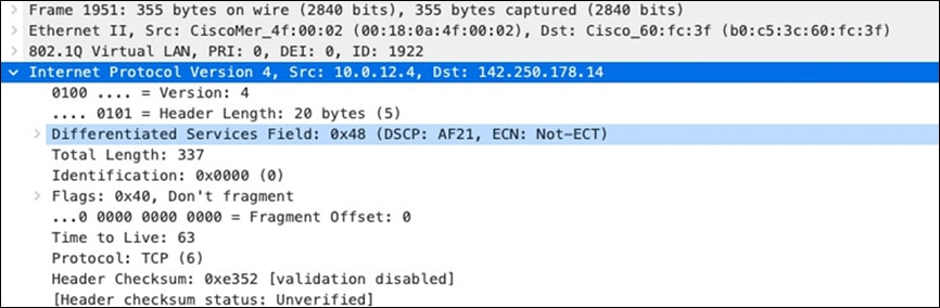
Client #2
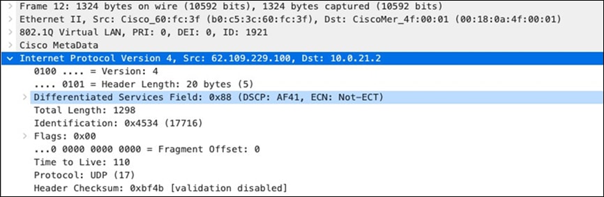
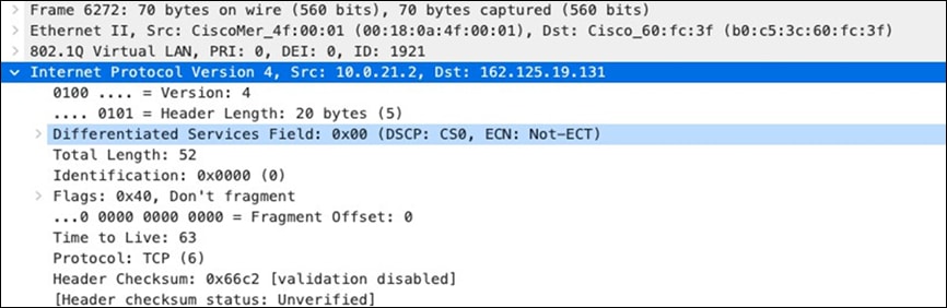
MX appliance Downlink pcaps
Client #1
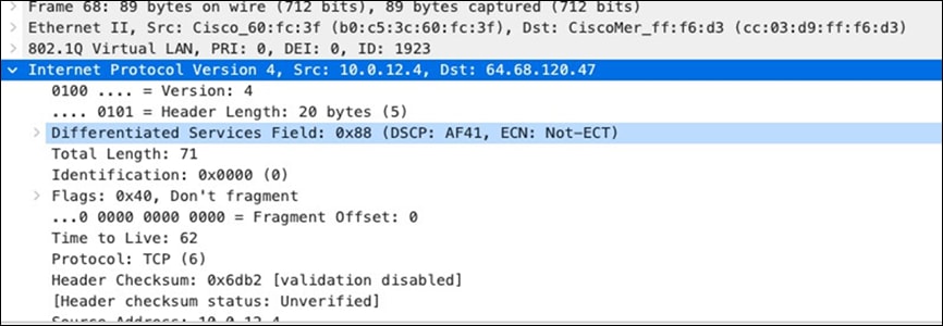
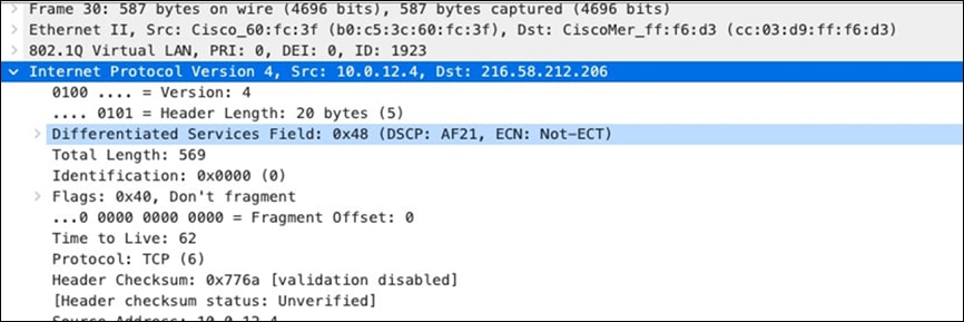
Client #2
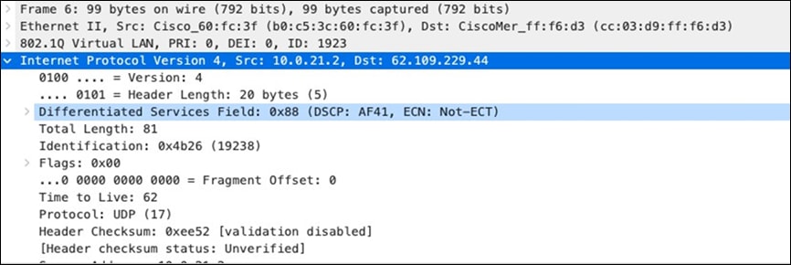
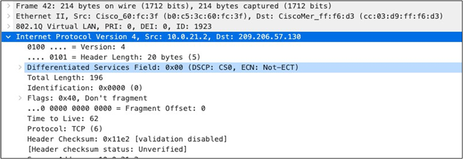
Layer 3 Roaming with concentrator
The previous design which extends the Layer 3 domain to the Access Layer offered several benefits but one of the drawbacks was that VLANs cannot span between different stacks and therefore roaming is restricted within a single zone/closet. As such, to enable Layer 3 roaming in this Campus network the SSID needs to be tunneled to a Meraki MX operating as a concentrator. Please see the below diagram for the logical architecture of this design option:
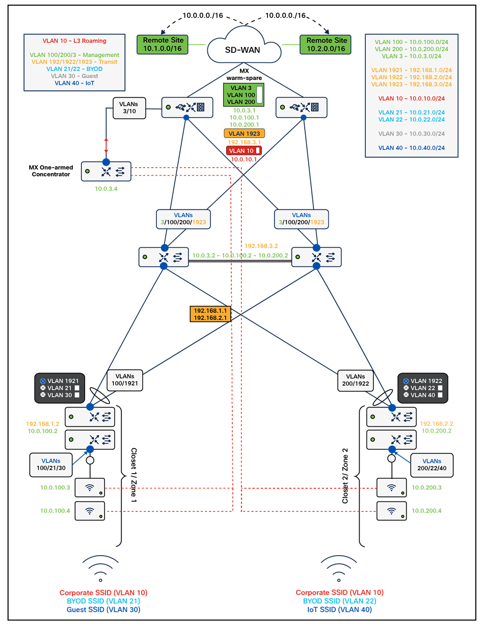
The design will not change any of the elements previously configured except that the Acme Corp SSID will be configured in Layer 3 Roaming with Concentrator mode which requires having a Meraki MX Appliance configured as a concentrator. Subsequently, VLANs 11 and 12 will not be required anymore and the SVI for the new Corp VLAN will move to the WAN Edge MX. The WAN Edge MX in this case needs to provide DHCP services to roaming clients.
| Tech Tip: Please note that the MX concentrator in the above diagram was plugged directly into the MX WAN Edge appliance on port 3. Alternatively, this could have been plugged on the C9500 Core Stack which could be also beneficial should you wish to use warm-spare concentrators. In this case, please make sure that the switchports where these concentrator(s) are plugged on the C9500 Core Stack are configured as trunk ports and that the Roaming VLAN is allowed. For more information on MX concentrator sizing, please refer to this article. |
| Tech Tip: Please note that though it is possible to use an MX appliance in routed mode to concentrate the SSID, it will not be possible in the case of this design. The reason is that the AutoVPN tunnel will fail to establish as it terminates on the MX uplink interface (on the WAN side, not the LAN side). |
Special considerations for this design option:
● APs will create a Layer 2 AutoVPN tunnel to the MX Concentrator using their management IP address
● Radius requests from the Acme Corp SSID will have the NAS ID referring to the AP's management IP address where the client is attached however the device IP in the request will refer to the uplink IP address of the MX concentrator (e.g. 10.0.3.4 in this case)
● The Radius server (in our case Cisco ISE) will require an IP route to the MX concentrator's uplink IP address (e.g. 10.0.3.4)
● The Radius server will also need to be configured with the concentrator as a network device since the Radius requests will have its IP address as the device IP address (Otherwise testing 802.1x auth failed)
● If the Radius server is reachable from the Campus via VPN tunnel (e.g. AutoVPN) then the Concentrator's uplink IP address/network will need to be advertised via the VPN as well
The following steps will outline the configuration changes to enable Layer 3 Roaming in this Campus LAN:
1. Please ensure that you have an additional MX appliance in your dashboard and the appropriate license(s) claimed
2. Add the appliance(s) to a new network (e.g. Roaming)
3. Navigate to your Roaming network
4. Navigate to Security and SD-WAN > Configure > Addressing and VLANs
5. Select Passthrough or VPN Concentrator and click Save at the bottom of the page
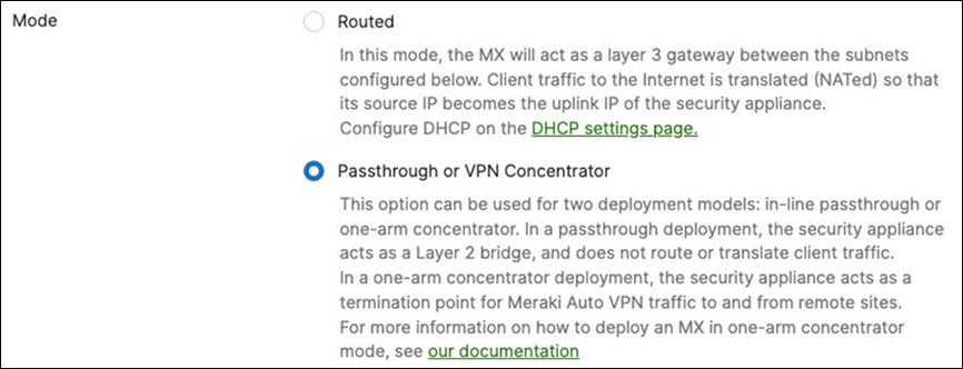
6. Navigate to your Campus Network
7. Navigate to Security and SD-WAN > Addressing and VLANs and create a new VLAN for the Roaming SSID (e.g. VLAN 10)
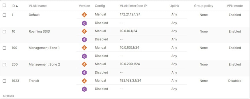
8. Navigate further down the page to the Per-port VLAN settings and configure the port connecting the MX Concentrator (e.g. Port 3 in this design) with a Native VLAN (e.g. VLAN 3) and allow both the native VLAN and the Roaming SSI VLAN that you have just created in the above step

9. Click Save at the bottom of the page
10. Plug your MX Concentrator and connect it to the designated port (Port #3) on the WAN Edge MX. Please note that the MX concentrator needs to be connected ONLY via a single uplink (No other uplinks or LAN ports)
11. Once the MX Concentrator comes online on dashboard you can proceed to the next step (Waiting for the concentrator to come online will allow you to test the tunnel connectivity from the APs to the Concentrator)
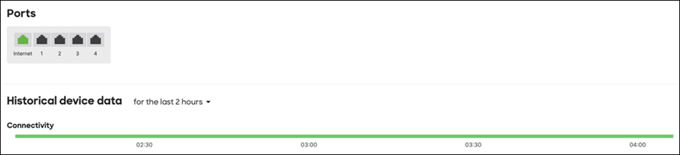
12. Navigate to Wireless > Configure > Access control and from the top drop-down menu select the Acme Corp SSID
13. Navigate further down the page and under the Client IP assignment menu, select the Layer 3 with Concentrator option then choose VLAN 10 as the terminating VLAN for this SSID. Click Save at the bottom of the page.

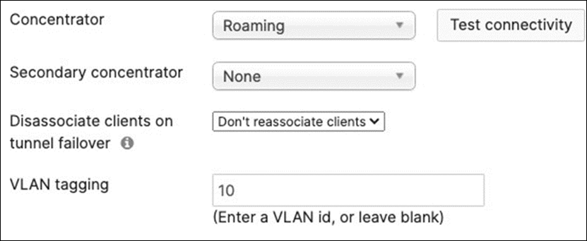
14. To test the Tunnel connectivity, click on Test Connectivity
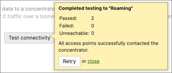
● The test above will check the IP connectivity between the APs with the Acme Corp SSID (AP's uplink IP address) and the MX concentrator (MX's uplink IP address) and return back how many APs passed the test (valid IP route) and how many failed (due to IP routing issues)
15. Navigate to Security and SD-WAN > Configure > Site-to-site VPN and enable the upstream network of the MX Concentrator in AutoVPN (e.g. VLAN 3 in our case)
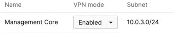
● As explained earlier, this step is essential for the Cisco ISE server to accept Access-Requests from the MX concentrator
16. After you have configured the appropriate routing on the Radius server side to allow it to communicate with VLAN 3, you can proceed with testing IP connectivity between the MX concentrator and the Radius Server
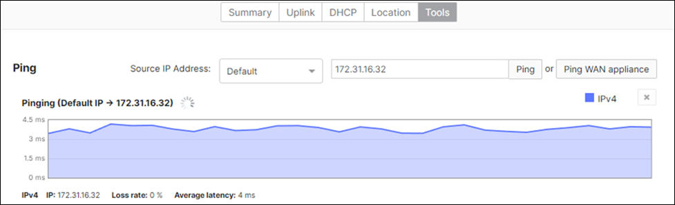
● Please note that you won't be able to ping unless the Upstream network of the MX Concentrator has been enabled in AutoVPN and that the Radius Server has an IP route back to the Campus LAN. Please check the following example for this implementation of Cisco ISE in AWS where a route has been added on the VPC where the ISE server resides

17. After you have added the MX concentrator on your Radius server as a network device, you can test using a client attached to the Acme Corp SSID
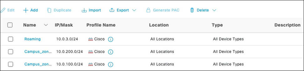
Testing and Verification:
The following client was used for testing and verification:
| Device |
Mac address |
IP address |
| iPhone |
12:34:5c:8c:16:04 |
10.0.10.2 |
Device Connectivity

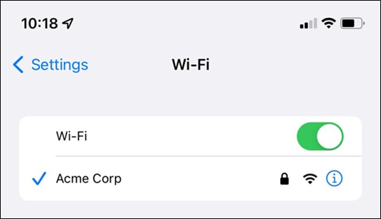
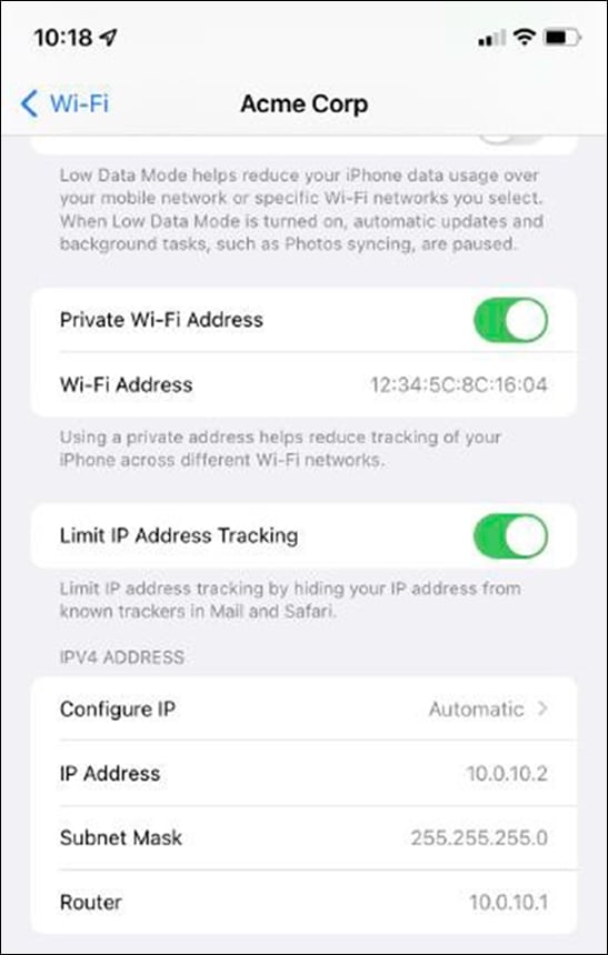
| Note: As seen above, the Client successfully associated with the Acme Corp SSID and acquired an IP address in VLAN 10 (10.0.10.2) |
Radius Authentication
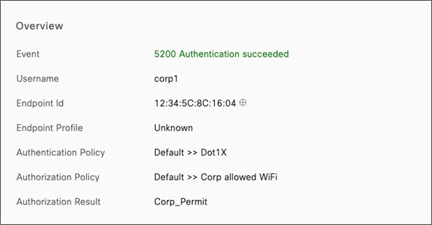
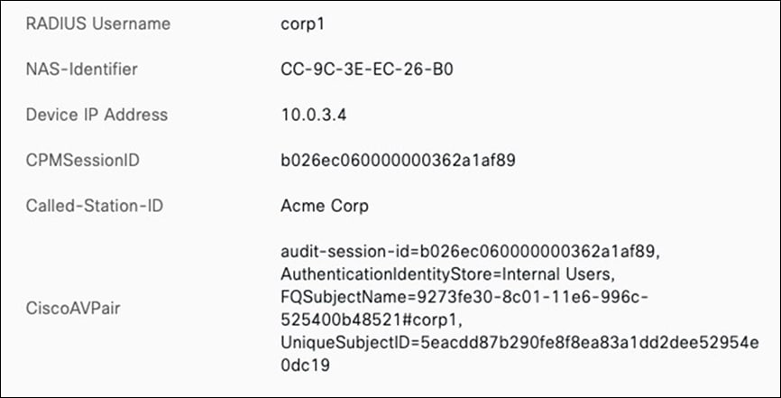
| Tech Tip: As seen above from the Cisco ISE live logs, 802.1x authentication was successful and the client was permitted on the network. Please note the Device IP Address field which shows 10.0.3.4 (MX Concentrator uplink IP address in this case) |
Layer 3 Wireless Roaming

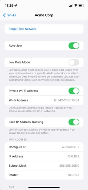


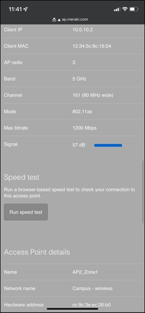
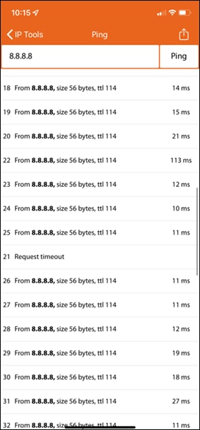
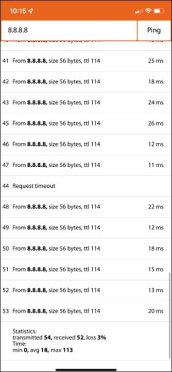
| Note: Roaming back and forth between APs caused a brief packet loss of one packet |