Comprensión y configuración del protocolo STP en switches Catalyst
Opciones de descarga
-
ePub (107.9 KB)
Visualice en diferentes aplicaciones en iPhone, iPad, Android, Sony Reader o Windows Phone -
Mobi (Kindle) (131.2 KB)
Visualice en dispositivo Kindle o aplicación Kindle en múltiples dispositivos
Lenguaje no discriminatorio
El conjunto de documentos para este producto aspira al uso de un lenguaje no discriminatorio. A los fines de esta documentación, "no discriminatorio" se refiere al lenguaje que no implica discriminación por motivos de edad, discapacidad, género, identidad de raza, identidad étnica, orientación sexual, nivel socioeconómico e interseccionalidad. Puede haber excepciones en la documentación debido al lenguaje que se encuentra ya en las interfaces de usuario del software del producto, el lenguaje utilizado en función de la documentación de la RFP o el lenguaje utilizado por un producto de terceros al que se hace referencia. Obtenga más información sobre cómo Cisco utiliza el lenguaje inclusivo.
Acerca de esta traducción
Cisco ha traducido este documento combinando la traducción automática y los recursos humanos a fin de ofrecer a nuestros usuarios en todo el mundo contenido en su propio idioma. Tenga en cuenta que incluso la mejor traducción automática podría no ser tan precisa como la proporcionada por un traductor profesional. Cisco Systems, Inc. no asume ninguna responsabilidad por la precisión de estas traducciones y recomienda remitirse siempre al documento original escrito en inglés (insertar vínculo URL).
Contenido
Introducción
Este documento describe cómo utilizar el protocolo de árbol de extensión (STP) para asegurarse de que no cree bucles cuando tenga rutas redundantes en la red.
Prerequisites
Requirements
No hay requisitos específicos para este documento.
Componentes Utilizados
La información que contiene este documento se basa en las siguientes versiones de software y hardware.
-
Cisco Catalyst 5500/5000 switches
-
Un cable de consola adecuado para la Supervisor Engine en el switch
-
Six Catalyst 5509 Switches
Los principios del árbol de expansión que presenta el documento se aplican a casi todos los dispositivos que admiten STP.
La información que contiene este documento se creó a partir de los dispositivos en un ambiente de laboratorio específico. Todos los dispositivos que se utilizan en este documento se pusieron en funcionamiento con una configuración verificada (predeterminada). Si tiene una red en vivo, asegúrese de entender el posible impacto de cualquier comando.
Antecedentes
Spanning Tree Protocol (STP) es un protocolo de capa 2 que se ejecuta en bridges y switches. La especificación para STP es IEEE 802.1D. El propósito principal de STP es garantizar que usted no cree loops cuando tenga trayectorias redundantes en su red. Los loops son fatales para una red.
Las configuraciones en este documento se aplican a Catalyst 2926G, 2948G, 2980G, 4500/4000, 5500/5000 y 6500/6000 Switches que ejecutan el Catalyst OS (CatOS). Consulte estos documentos para obtener información sobre la configuración de STP en otras plataformas de switch:
-
STP y MST (switches Catalyst 6500/6000 que ejecutan Cisco IOS®Software)
-
Configuración de STP y MST (switches Catalyst 4500/4000 que ejecutan Cisco IOS Software)
Diagrama de la red
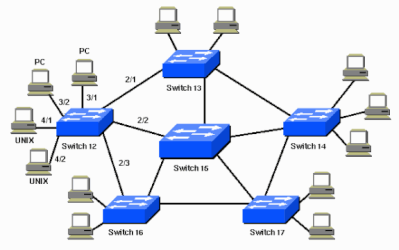
En este documento, se utiliza esta configuración de red:
Conceptos
STP se ejecuta en bridges y switches en conformidad con 802.1D. Hay diferentes tipos de STP, pero 802.1D es el más popular y el que se ha implementado ampliamente. Usted implementa STP en bridges y switches para prevenir loops en la red. Utilice STP en situaciones donde desee links redundantes, pero no loops. Los links redundantes son tan importantes como los de respaldo en el caso de un failover en una red. Una falla en un link primario activa los links de respaldo para que los usuarios puedan continuar utilizando la red. Sin STP en los bridges y los switches, dicha falla podría generar un loop. Si dos switches conectados ejecutan diferentes tipos de STP, requieren diferentes controles para converger. Cuando se utilizan diferentes tipos en los switches, se crean problemas de control entre los estados de bloqueo y reenvío. Por lo tanto, se recomienda utilizar los mismos tipos de STP. Considere esta red:
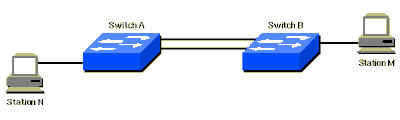
En esta red, se planifica un link redundante entre el Switch A y el Switch B. Sin embargo, esta configuración crea la posibilidad de un loop de bridging. Por ejemplo, un paquete de multicast o broadcast que transmite de la Estación M y está destinado a la Estación N continúa simplemente circulando entre ambos switches.
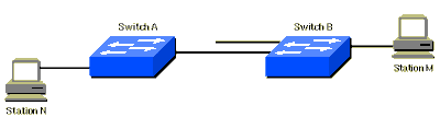
Sin embargo, cuando STP se ejecuta en ambos switches, la red es lógicamente similar a lo siguiente:
Esta información se aplica a la situación del Diagrama de la Red:
-
El Switch 15 es el switch de backbone.
-
Los Switches 12, 13, 14, 16 y 17 son los que conectan a las estaciones de trabajo y a las PC.
-
La red define estas VLAN:
-
1
-
200
-
201
-
202
-
203
-
204
-
-
El nombre de dominio de VLAN Trunk Protocol (VTP) es STD-Doc.
Para proporcionar esta redundancia de trayectorias deseada y evitar, a su vez, una condición de loop, STP define un árbol que expande todos los switches en una red extendida. STP fuerza ciertas trayectorias de datos redundantes a un estado de standby (bloqueado) y deja a otras trayectorias en un estado de reenvío. Si un link en el estado de reenvío deja de estar disponible, STP reconfigura la red y vuelve a rutear las trayectorias de datos a través de la activación de la trayectoria de standby adecuada.
Descripción de la Tecnología
Con STP, la clave es elegir para todos los switches en la red un root bridge que se convierta en el centro de la red. Las demás decisiones sobre la red, como qué puerto se debe bloquear y qué puerto se debe colocar en el modo de reenvío, se toman desde la perspectiva de este root bridge. Un entorno conmutado, que es diferente a un entorno de bridge, es más probable que trate varias VLAN. Cuando usted implementa un root bridge en una red de switching, usualmente se refiere al root bridge como el switch root. Cada VLAN debe tener su propio root bridge porque cada VLAN es un dominio de broadcast separado. Todas las roots de las diferente VLAN pueden residir en un un solo switch o en varios switches.

Nota: La selección del switch raíz para una VLAN determinada es muy importante. Puede elegir el switch root, o bien puede dejar que los switches decidan, lo cual es un riesgo. Si usted no controla el proceso de selección de la root, puede haber trayectorias no muy óptimas en su red.
Todos los switches intercambian información para su uso en la selección del switch root y para la configuración subsiguiente de la red. Las unidades de datos de protocolo de bridge (BPDU) llevan esta información. Cada switch compara los parámetros en la BPDU que el switch envía a un vecino con los parámetros en la BPDU que el switch recibe del vecino.
En el proceso de selección de la root de STP, menos es mejor. Si el Switch A anuncia un ID de root que es un número menor que el ID de root que anuncia el Switch B, la información del Switch A es mejor. El Switch B detiene el anuncio de su ID de root y acepta el ID de root del Switch A.
Refiérase a Funciones Opcionales de STP para obtener más información sobre algunas de las funciones opcionales de STP, como:
-
PortFast
-
Protección de raíz
-
Protección de loop
-
Protección BPDU
Funcionamiento de STP
Tarea
Prerequisites
Antes de configurar STP, seleccione un switch para que sea la root de spanning tree. No es necesario que este switch sea el más potente, pero elija el switch más centralizado en la red. Todo el flujo de datos en la red es desde la perspectiva de este switch. Además, elija el switch menos perturbado en la red. Los switches de backbone suelen servir como la root de spanning tree porque estos switches generalmente no conectan a estaciones extremas. También es menos probable que los movimientos y los cambios dentro de la red afecten a estos switches.
Una vez que haya decidido el switch root, configure las variables adecuadas para designar el switch como el switch root. La única variable que debe establecer es el bridge priority . Si el switch tiene una prioridad de bridge más baja que las de los demás switches, los otros switches seleccionan automáticamente el switch como el switch root.
Clientes (Estaciones Extremas) en los Puertos de Switch
También puede ejecutar el set spantree portfast comando, por puerto. Cuando habilita la portfast variable en un puerto, el puerto inmediatamente cambia del modo de bloqueo al modo de reenvío. La habilitación de portfast ayuda a evitar tiempos de espera en los clientes que utilizan Novell Netware o usan DHCP para obtener una dirección IP. Sin embargo, no utilice este comando cuando tenga una conexión de switch a switch. En este caso, el comando puede generar un loop. La demora de 30 a 60 segundos que ocurre durante la transición del modo de bloqueo al modo de reenvío previene una condición de loop temporal en la red cuando usted conecta dos switches.
Deje la mayoría de las otras variables de STP con sus valores predeterminados.
Reglas de Funcionamiento
En esta sección, se enumeran las reglas para el funcionamiento de STP. Cuando los switches aparecen por primera vez, comienzan el proceso de selección del switch root. Cada switch transmite una BPDU al switch directamente conectado por VLAN.
Cuando la BPDU sale a través de la red, cada switch compara la BPDU que el switch envía con la BPDU que el switch recibe de los vecinos. Los switches luego se ponen de acuerdo en qué switch es el switch root. El switch con el ID de bridge más bajo en la red gana este proceso de elección.
Nota: Recuerde que se identifica un switch raíz por VLAN. Después de la identificación del switch root, los switches se adhieren a estas reglas.
-
Regla de STP 1: todos los puertos del switch root deben estar en el modo de reenvío.
Nota: En algunos casos extremos, que implican puertos de loop automático, hay una excepción a esta regla.
Después, cada switch determina la mejor trayectoria para llegar a la root. Los switches determinan esta trayectoria mediante una comparación de la información en todas las BPDU que los switches reciben en todos los puertos. El switch utiliza el puerto con la menor cantidad de información en la BPDU para llegar al switch root; el puerto con la menor cantidad de información en la BPDU es el puerto root. Una vez que un switch haya determinado el puerto root, el switch pasará a la regla 2.
-
Regla de STP 2: el puerto root se debe configurar en el modo de reenvío.
Además, los switches en cada segmento LAN se comunican entre sí para determinar qué switch es mejor utilizar para mover datos de ese segmento al root bridge. Este switch se denomina switch designado.
-
Regla de STP 3: en un solo segmento LAN, el puerto del switch designado que conecta a ese segmento LAN se debe colocar en el modo de reenvío.
-
Regla de STP 4: el resto de los puertos en todos los switches (específicos de VLAN) se deben colocar en el modo de bloqueo. La regla se aplica solamente a los puertos que conectan a otros bridges o switches. STP no afecta a los puertos que conectan a las estaciones de trabajo o a las PC. Estos puertos siguen con el reenvío.
Nota: La adición o eliminación de VLAN cuando el STP se ejecuta en el modo de árbol de expansión por VLAN (PVST / PVST+) activa el recálculo del árbol de expansión para esa instancia de VLAN y el tráfico se interrumpe solamente para esa VLAN. Las otras partes de VLAN de un link trunk pueden reenviar el tráfico normalmente. La adición o la remoción de VLAN para una instancia de Multiple Spanning Tree (MST) existente acciona el recálculo de spanning tree para esa instancia y el tráfico se interrumpe para todas las partes de VLAN de esa instancia de MST.
Nota: De forma predeterminada, el spanning tree se ejecuta en cada puerto. La función de spanning tree no se puede desactivar en los switches por puerto. Si bien no se recomienda, puede desactivar STP por VLAN o de forma global en el switch. Se debe tener extremo cuidado cada vez que inhabilita el spanning tree porque esto crea loops de Capa 2 dentro de la red.
Step-by-Step Instructions
Complete estos pasos:
-
Ejecute el show version comando para mostrar la versión de software que ejecuta el switch.
Nota: Todos los switches ejecutan la misma versión de software.
Switch-15> (enable)show version
WS-C5505 Software, Version McpSW: 4.2(1) NmpSW: 4.2(1)
Copyright (c) 1995-1998 by Cisco Systems
NMP S/W compiled on Sep 8 1998, 10:30:21
MCP S/W compiled on Sep 08 1998, 10:26:29
System Bootstrap Version: 5.1(2)
Hardware Version: 1.0 Model: WS-C5505 Serial #: 066509927
Mod Port Model Serial # Versions
--- ---- ---------- --------- ----------------------------------------
1 0 WS-X5530 008676033 Hw : 2.3
Fw : 5.1(2)
Fw1: 4.4(1)
Sw : 4.2(1)
En esta situación, el Switch 15 es la mejor opción para el switch root de la red para todas las VLAN porque el Switch 15 es el switch de backbone.
-
Ejecute el set spantree root vlan_id comando para establecer la prioridad del switch en 8192 para la VLAN o VLAN que vlan_id especifique el .
Nota: La prioridad predeterminada para los switches es 32768. Cuando establece la prioridad con este comando, fuerza la selección del Switch 15 como el switch root porque el Switch 15 tiene la prioridad más baja.
Switch-15> (enable)set spantree root 1
VLAN 1 bridge priority set to 8192.
VLAN 1 bridge max aging time set to 20.
VLAN 1 bridge hello time set to 2.
VLAN 1 bridge forward delay set to 15.
Switch is now the root switch for active VLAN 1.
Switch-15> (enable)
Switch-15> (enable)set spantree root 200
VLAN 200 bridge priority set to 8192.
VLAN 200 bridge max aging time set to 20.
VLAN 200 bridge hello time set to 2.
VLAN 200 bridge forward delay set to 15.
Switch is now the root switch for active VLAN 200.
Switch-15> (enable)
Switch-15> (enable)set spantree root 201
VLAN 201 bridge priority set to 8192.
VLAN 201 bridge max aging time set to 20.
VLAN 201 bridge hello time set to 2.
VLAN 201 bridge forward delay set to 15.
Switch is now the root switch for active VLAN 201.
Switch-15> (enable)
Switch-15> (enable)set spantree root 202
VLAN 202 bridge priority set to 8192.
VLAN 202 bridge max aging time set to 20.
VLAN 202 bridge hello time set to 2.
VLAN 202 bridge forward delay set to 15.
Switch is now the root switch for active VLAN 202.
Switch-15>
Switch-15> (enable)set spantree root 203
VLAN 203 bridge priority set to 8192.
VLAN 203 bridge max aging time set to 20.
VLAN 203 bridge hello time set to 2.
VLAN 203 bridge forward delay set to 15.
Switch is now the root switch for active VLAN 203.
Switch-15>
Switch-15> (enable)set spantree root 204
VLAN 204 bridge priority set to 8192.
VLAN 204 bridge max aging time set to 20.
VLAN 204 bridge hello time set to 2.
VLAN 204 bridge forward delay set to 15.
Switch is now the root switch for active VLAN 204.
Switch-15> (enable)
La versión más corta del comando tiene el mismo efecto, como muestra este ejemplo:
Switch-15> (enable)set spantree root 1,200-204
VLANs 1,200-204 bridge priority set to 8189.
VLANs 1,200-204 bridge max aging time set to 20.
VLANs 1,200-204 bridge hello time set to 2.
VLANs 1,200-204 bridge forward delay set to 15.
Switch is now the root switch for active VLANs 1,200-204.
Switch-15> (enable)
El set spantree priority comando proporciona un tercer método para especificar el switch root:
Switch-15> (enable)set spantree priority 8192 1
Spantree 1 bridge priority set to 8192.
Switch-15> (enable)
Nota: En esta situación, todos los switches se iniciaron con configuraciones despejadas. Por lo tanto, todos los switches comenzaron con una prioridad de bridge de 32768. Si usted no está seguro de que todos los switches en la red tengan una prioridad mayor que 8192, establezca la prioridad del root bridge deseado en 1.
-
Ejecute el set spantree portfast mod_num/port_num enable comando para configurar el parámetro PortFast en los switches 12, 13, 14, 16 y 17.
Nota: configure este parámetro sólo en los puertos que se conectan a estaciones de trabajo o PC. No habilite PortFast en ningún puerto que conecte a otro switch.
-
El Puerto 2/1 conecta al Switch 13.
-
El Puerto 2/2 conecta al Switch 15.
-
El Puerto 2/3 conecta al Switch 16.
-
Los Puertos 3/1 a 3/24 conectan a las PC.
-
Los Puertos 4/1 a 4/24 conectan a las estaciones de trabajo UNIX.
Con esta información como base, ejecute el set spantree portfastcomando en los puertos 3/1 a 3/24 y en los puertos 4/1 a 4/24:
Switch-12> (enable)set spantree portfast 3/1-24 enable
Warning: Spantree port fast start should only be enabled on ports connected to a single host. Connecting hubs, concentrators, switches, bridges, etc.
to a fast start port can cause temporary spanning-tree loops. Use with caution. Spantree ports 3/1-24 fast start enabled.
Switch-12> (enable) Switch-12> (enable)set spantree portfast 4/1-24 enable Warning: Spantree port fast start should only be enabled on ports connected to a single host. Connecting hubs, concentrators, switches, bridges, etc.
to a fast start port can cause temporary spanning-tree loops. Use with caution. Spantree ports 4/1-24 fast start enabled. Switch-12> (enable)
-
Ejecute el show spantree vlan_id comando para verificar que el Switch 15 sea la raíz de todas las VLAN apropiadas.
Con el resultado de este comando, compare la dirección MAC del switch que sea el switch root con la dirección MAC del switch desde el que ejecutó el comando. Si las direcciones coinciden, el switch en el que se encuentra es el switch root de la VLAN. Un puerto root que es 1/0 también indica que usted se encuentra en el switch root. Este es el resultado del comando de ejemplo:
Switch-15> (enable)show spantree 1
VLAN 1
spanning-tree enabled
spanning-tree type ieee
Designated Root 00-10-0d-b1-78-00
!--- This is the MAC address of the root switch for VLAN 1.
Designated Root Priority 8192
Designated Root Cost 0
Designated Root Port 1/0
Root Max Age 20 sec Hello Time 2 sec Forward Delay 15 sec
Bridge ID MAC ADDR 00-10-0d-b1-78-00
Bridge ID Priority 8192
Bridge Max Age 20 sec Hello Time 2 sec Forward Delay 15 sec
En este resultado, se muestra que el Switch 15 es la root designada en el spanning tree para la VLAN 1. La dirección MAC del switch root designado,00-10-0d-b1-78-00, es la misma que la dirección MAC del ID de bridge del Switch 15,00-10-0d-b1-78-00. Otro indicador de que este switch es la root designada es que el puerto root designado es 1/0.
En este resultado del Switch 12, el switch reconoce al Switch 15 como el switch Designated Rootpara la VLAN 1:
Switch-12> (enable)show spantree 1
VLAN 1
spanning-tree enabled
spanning-tree type IEEEDesignated Root 00-10-0d-b1-78-00
!--- This is the MAC address of the root switch for VLAN 1.
Designated Root Priority 8192
Designated Root Cost 19
Designated Root Port 2/3
Root Max Age 20 sec Hello Time 2 sec Forward Delay 15 sec
Bridge ID MAC ADDR 00-10-0d-b2-8c-00
Bridge ID Priority 32768
Bridge Max Age 20 sec Hello Time 2 sec Forward Delay 15 sec
Nota: La salida del comando show spantree vlan_id para los otros switches y VLAN también puede indicar que el Switch 15 es la raíz designada para todas las VLAN.
Verificación
En esta sección encontrará información que puede utilizar para comprobar que su configuración funciona correctamente.
-
show spantree vlan_id— Muestra el estado actual del spanning tree para este ID de VLAN, desde la perspectiva del switch en el que ejecuta el comando.
-
show spantree summary— Proporciona un resumen de los puertos de spanning tree conectados por VLAN.
Troubleshoot
En esta sección encontrará información que puede utilizar para solucionar problemas de configuración.
El Costo de Trayectoria de STP Cambia Automáticamente Cuando Se Cambia un Dúplex o una Velocidad de Puerto
STP calcula el costo de trayectoria según la velocidad de los medios (el ancho de banda) de los links entre los switches y el costo de puerto de cada trama de reenvío de puerto. El spanning tree selecciona el puerto root según el costo de trayectoria. El puerto con el costo de trayectoria más bajo hacia el root bridge se convierte en el puerto root. El puerto root siempre está en el estado de reenvío.
Si se cambia la velocidad/el dúplex del puerto, el spanning tree recalcula el costo de trayectoria automáticamente. Un cambio en el costo de trayectoria puede cambiar la topología del spanning tree.
Consulte la sección Calcular y Asignar Costos de Puerto de Configurar Spanning Tree para obtener más información sobre cómo calcular el costo del puerto.
Comandos para Troubleshooting
Nota: Consulte Información Importante sobre Comandos Debug antes de utilizar los comandos debug.
-
show spantree vlan_id: muestra el estado actual del árbol de expansión para este ID de VLAN, desde la perspectiva del switch en el que ejecuta el comando.
-
show spantree summary: proporciona un resumen de los puertos de árbol de extensión conectados por VLAN.
-
show spantree statistics: muestra información estadística del árbol de extensión.
-
show spantree backbonefast: muestra si la función de convergencia de BackboneFast del árbol de extensión está activada.
-
show spantree blockedports: muestra sólo los puertos bloqueados.
-
show spantree portstate: permite determinar el estado actual del árbol de extensión de un puerto Token Ring dentro de un árbol de extensión.
-
show spantree portvlancost—muestra el costo del trayecto para las VLAN en un puerto.
-
show spantree uplinkfast—muestra las configuraciones uplinkfast.
Resumen de Comandos
Sintaxis:
show version
Según se utiliza en este documento:
show version
Sintaxis:
set spantree root [vlan_id]
Según se utiliza en este documento:
set spantree root 1
set spantree root 1,200-204
Sintaxis:
set spantree priority [vlan_id]
Según se utiliza en este documento:
set spantree priority 8192 1
Sintaxis:
set spantree portfast mod_num/port_num {enable | disable}
Según se utiliza en este documento:
set spantree portfast 3/1-24 enable
Sintaxis:
show spantree [vlan_id]
Según se utiliza en este documento:
show spantree
Información Relacionada
Historial de revisiones
| Revisión | Fecha de publicación | Comentarios |
|---|---|---|
3.0 |
08-May-2023 |
Recertificación |
2.0 |
07-Apr-2022 |
Se quitó un vínculo roto. |
1.0 |
11-Dec-2019 |
Versión inicial |
Contribución realizada por
- yanlisshant
- jespeteranmohamm
 Comentarios
Contacte a Cisco
- Abrir un caso de soporte

- (Requiere un Cisco Service Contract)